
Lens driving device applying electromagnetic thrust force

A lens driving device, electromagnetic thrust technology, applied in the directions of electromechanical devices, installation, electrical components, etc., can solve the problems of difficult miniaturization of the lens module, inability to use reflow assembly, etc., to achieve simple production and assembly, improved reliability, and cost. low cost effect

Inactive Publication Date: 2009-10-14
E PIN OPTICAL IND
View PDF25 Cites 6 Cited by
  • Summary
  • Abstract
  • Description
  • Claims
  • Application Information

AI Technical Summary

Problems solved by technology

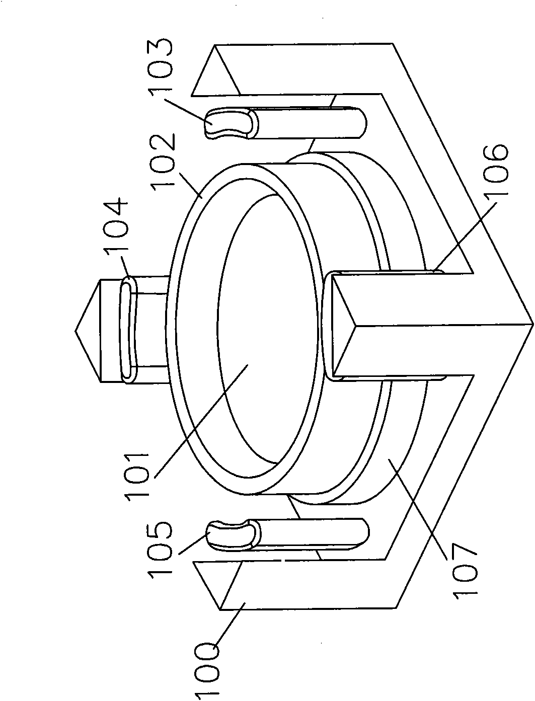
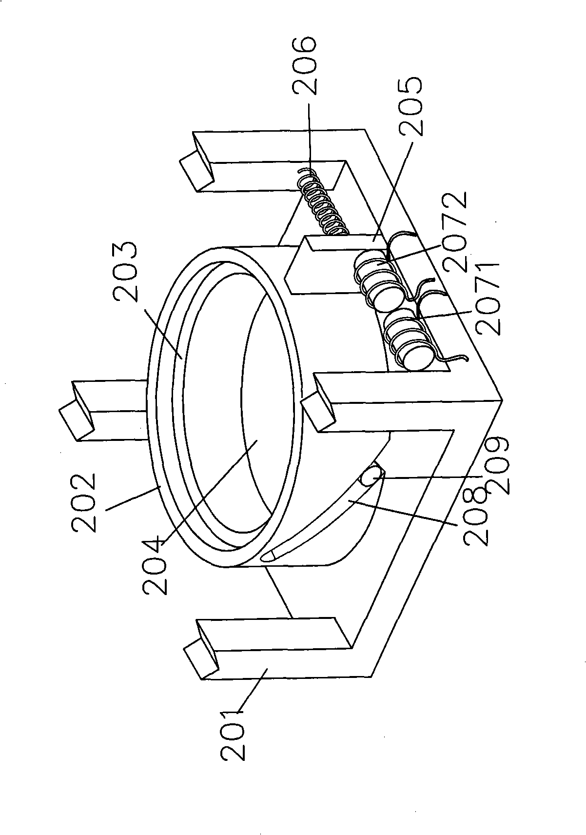
[0006] The purpose of the present invention is to overcome the defects existing in the existing lens module, and provide a new type of lens driving device using electromagnetic thrust, the technical problem to be solved is to make it solve the complex structure of the existing known technology lens The module is not easy to miniaturize, simplify, and cannot be assembled by reflow soldering, which is very suitable for practical use

Method used


Image

  • Lens driving device applying electromagnetic thrust force
  • Lens driving device applying electromagnetic thrust force
  • Lens driving device applying electromagnetic thrust force

Examples


Embodiment Construction

[0048] In order to further explain the technical means and effects of the present invention to achieve the intended purpose of the invention, the specific implementation, structure and characteristics of the lens driving device using electromagnetic thrust proposed according to the present invention will be described below in conjunction with the accompanying drawings and preferred embodiments. And its effect, detailed description is as follows.

[0049] The embodiments disclosed below of the present invention are described for the main components of the lens driving device using electromagnetic thrust in the present invention. Therefore, the embodiments disclosed below of the present invention are applied to an autofocus or zoom lens module. , but as far as the lens module with autofocus or zoom function is concerned, except for the lens driving device using electromagnetic thrust disclosed by the present invention, other structures are generally notified technologies, so peop...


PUM


Abstract

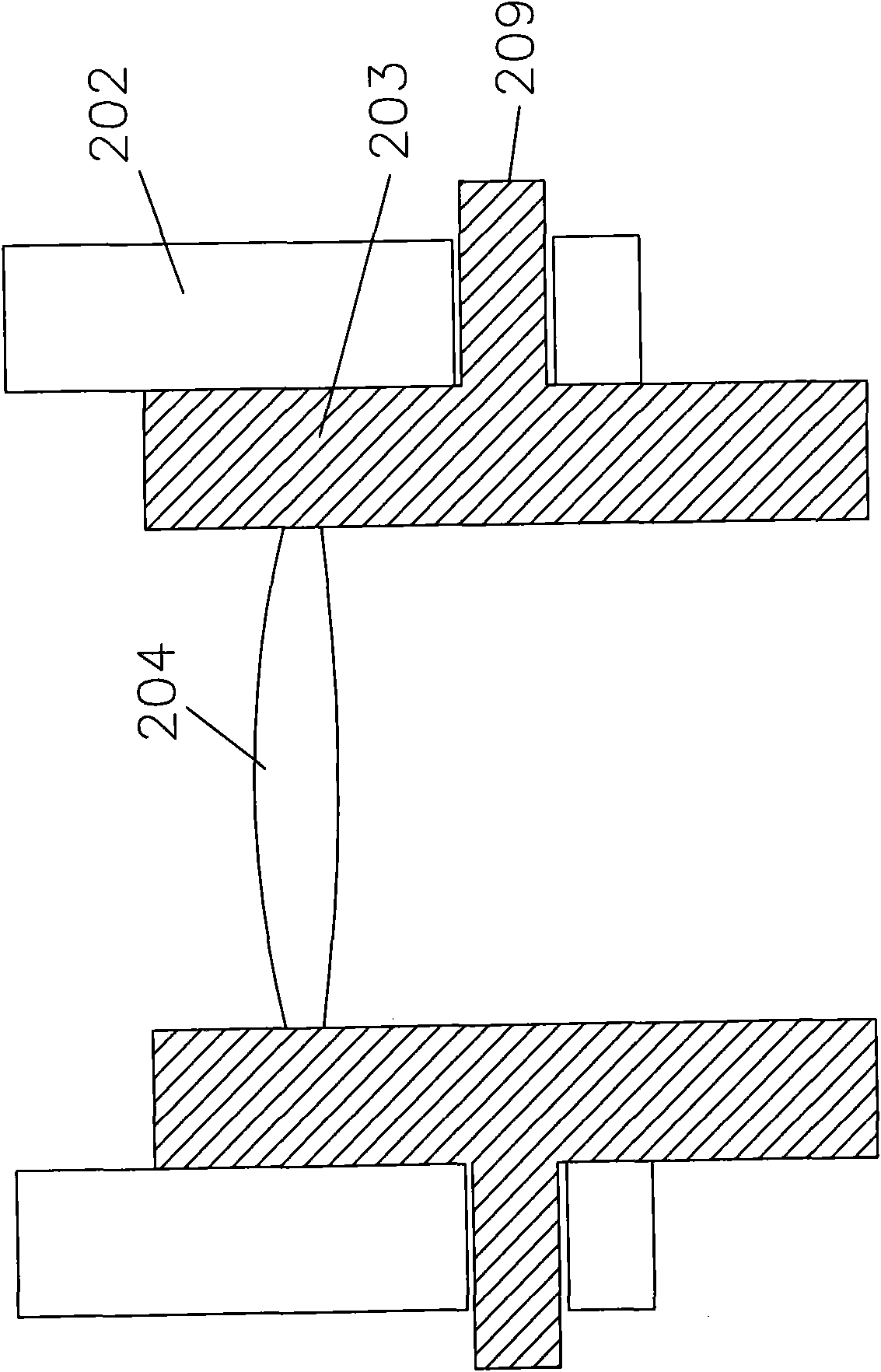
The invention relates to a lens driving device applying electromagnetic thrust force, which comprises a stand body, a sleeve, a lens clamping part, a lens, a push plate, a plurality of electromagnets and an elastic element, wherein the sleeve and the stand body are combined and fixed so that the sleeve can be rotated on the stand body, and the sleeve is provided with a first pushing mechanism; the lens clamping part is provided with a second pushing mechanism and connected with the sleeve by the second pushing mechanism and the first pushing mechanism; the lens is combined and fixed in the lens clamping part; the push pate is positioned on the outer wall of the sleeve; the electromagnets are respectively arranged on the stand body and the push plate, and the elastic element is connected with the sleeve and the stand body. By means of the repulsion force or the suction force in the magnetic field formed by electrifying the electromagnets, the sleeve is pushed to rotate, and the second pushing mechanism is actuated by the first pushing mechanism to drive the lens clamping part to move between a fist position and a second position. The invention is convenient for the miniaturization and the simplification of a lens module and can improve the probability of mass production.

Description

technical field [0001] The present invention relates to a lens driving device using electromagnetic thrust, which is applied to an autofocus or zoom lens group, in particular to a lens driving device that utilizes an electromagnet to generate thrust, and drives and controls the lens to slide and move through a thrust and a push-up mechanism. bit. Background technique [0002] Due to the limited space of the autofocus or zoom lens modules used in digital cameras, their devices must meet the conditions of lightness, thinness, and shortness, and must be precise and durable. Most of the traditional auto-focus or zoom lens modules use voice coil motors (VCM), piezoelectric motors, or coil electromagnetic force to drive the lens group, such as US patents US7,295,388, US6,654,185, and US7,298,562, which use multiple groups Electromagnets are used to control the displacement of the lens in different directions; or as in US2007 / 0097532 and US2004 / 0130808, which control the direction...

Claims


Application Information

Patent Timeline
Patent Type & Authority Applications(China)
IPC IPC(8): G02B7/09G02B7/04H02K33/18
Inventor 游腾健
Owner E PIN OPTICAL IND
Learn More