Floor rail type sliding door structure

A technology for ground rails and sliding doors, which is applied in door/window fittings, building structure, and wing fan layout, etc., can solve the problems of wasting wood resources, poor sound insulation, heat insulation and light transmittance, and falling off rollers. Save wood resources, enhance the viewing effect, and avoid the effect of loosening and deformation

Active Publication Date: 2012-01-11
CHANGSHU ZHONGXINBUILDING MATERIAL CO LTD
View PDF13 Cites 0 Cited by
  • Summary
  • Abstract
  • Description
  • Claims
  • Application Information

AI Technical Summary

Problems solved by technology

[0003] The applicant believes that none of the above-mentioned patents and patent application technologies involves the following technical problems in the current sliding door structure: first, the connection between the vertical frame and the upper and lower frames is unreliable and there is a risk of dismemberment during use; The second is that the vertical frame and the upper and lower frames appear in the form of metal materials such as aluminum extrusions, or in the form of pure wood. It makes up for the lack of the former, but consumes a large amount of wood. For example, in order to connect the door body and the frame body with tenon joint effect, it is necessary to make grooves on the frame body, which not only wastes wood resources, but also requires a lot of processing work; the third is The sound insulation, heat insulation and light transmittance are poor, and it does not have the effect of energy saving and noise reduction; the fourth is that the cooperation between the floor rail roller mechanism and the lower frame is insufficient, usually because the rollers are directly set on the bottom of the lower frame, which leads to damage to the lower frame and make the roller fall off

Method used


Image

  • Floor rail type sliding door structure
  • Floor rail type sliding door structure
  • Floor rail type sliding door structure

Examples


Embodiment Construction

[0018] In order to enable the examiners of the Patent Office, especially the public, to understand the technical essence and beneficial effects of the present invention more clearly, the applicant will give a detailed description in the following examples in the form of examples in conjunction with the drawings, but the description of the examples is not a reference to the present invention. The limitations of the inventive solution, any equivalent transformations made according to the concept of the invention that are merely formal rather than substantive should be regarded as the scope of the technical solution of the invention.

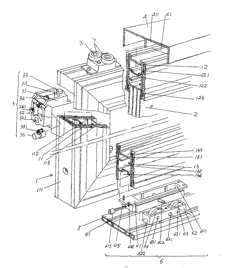
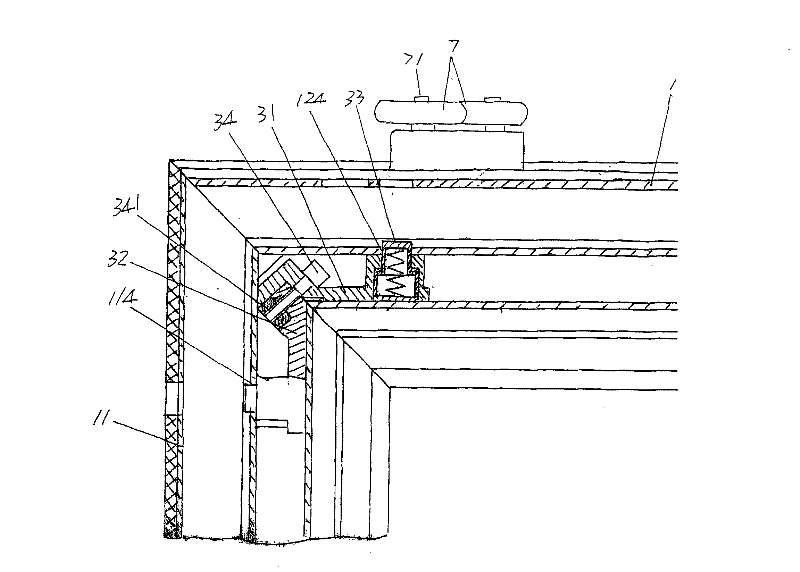
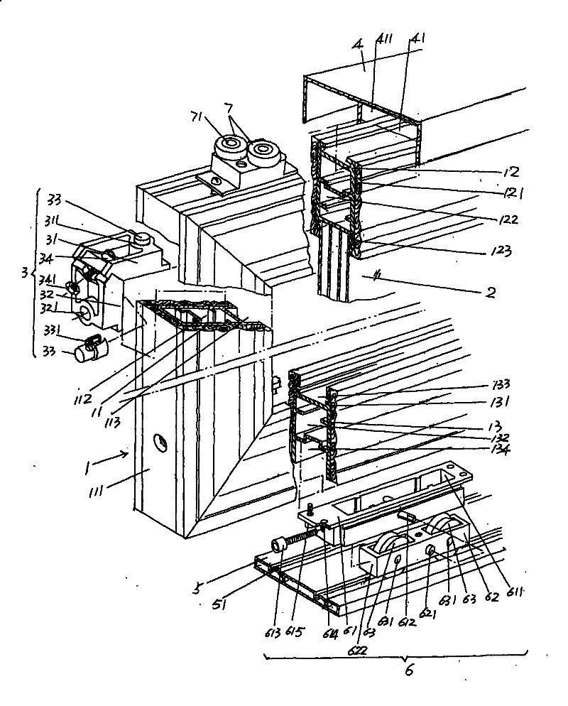
[0019] See figure 1 , According to professional common sense and common sense of life, there are usually two sliding doors. Although only one is shown in the figure, it will not confuse the understanding. Each sliding door is assembled by frame 1 and door 2. . In this embodiment, the frame body 1 is each composed of a pair of vertical frames 11, an up...


PUM


Abstract

The invention relates to a floor rail type sliding door structure, belonging to the technical field of sliding door and window component of building. The structure comprises a frame body, a door body arranged on the frame body, an upper and a lower lead rail plate, a group of floor rail roller wheel mechanisms and a group of upper guide wheels which are collocated in pairs, wherein, the frame bodycomprises a pair of longitudinal frames, an upper frame and a lower frame, and is characterized in that transitional coupling devices are respectively arranged at the splicing part between the upperframe and the longitudinal frames as well as the splicing part between the lower frame and the longitudinal frames; the outer walls of the pair of longitudinal frames are fixedly provided with a firstwooden protecting ornamental plates, the outer wall of the upper frame is fixedly provided with a second wooden protecting ornamental plate, and the outer wall of the lower frame is fixedly providedwith a third wooden protecting ornamental plate; the door body is constructed by at least two pieces of laminated glazing mosaic glass or low radiation hollow mosaic glass; the floor rail roller wheelmechanisms are held in the lower frame. The invention has the advantages that the upper and the lower frames are ensured to be fixedly connected with the longitudinal frames in a reliable way; the strength of the frame body can be guaranteed, the wood resource can be saved, and sight view effect can be improved; the energy is saved and the noise is reduced; the floor rail roller wheel mechanismsare matched with the lower frame in a reasonable way.

Description

Technical field [0001] The invention belongs to the technical field of building sliding door and window components, and specifically relates to a ground rail type sliding door structure. Background technique [0002] The application of sliding doors in buildings has a long history and is found in documents such as Chinese patent documents. For example, the utility model patent authorization announcement number CN2769460Y recommends the same-plane sliding door; and CN2766011Y introduces a built-in sliding door structure; For example, CN201103316Y discloses a new type of sandwich sliding door; another example is CN201083067Y with a double-opening and double-closing linkage sliding door; further, as CN101377109A discloses a glass sliding door device with good sliding performance; and even more such as the upper suspension sliding door recommended by CN201155267Y, and many more. [0003] The applicant believes that the above-mentioned patents and patent application technologies do not...

Claims


Application Information

Patent Timeline
Patent Type & Authority Patents(China)
IPC IPC(8): E06B3/46E05D13/00
Inventor 王卫东
Owner CHANGSHU ZHONGXINBUILDING MATERIAL CO LTD
Why Eureka
Try Eureka