
Anti-spattering bow fin of high-speed ship

An anti-splash and high-speed technology, which is applied in the field of ship fin device and hull structure of high-speed ships, can solve the problems of increasing manufacturing and use costs, and achieve the effect of reducing energy loss of the first wave and suppressing splash flow

Inactive Publication Date: 2009-10-07
JIANGSU UNIV OF SCI & TECH
View PDF1 Cites 14 Cited by
  • Summary
  • Abstract
  • Description
  • Claims
  • Application Information

AI Technical Summary

Problems solved by technology

This device has an adverse effect on the space arrangement and overall propulsion efficiency of the high-speed boat, in addition to increasing the cost of manufacturing and use

Method used


Image

  • Anti-spattering bow fin of high-speed ship
  • Anti-spattering bow fin of high-speed ship
  • Anti-spattering bow fin of high-speed ship

Examples


Embodiment Construction

[0026] The present invention will be further described below with reference to the drawings and embodiments.

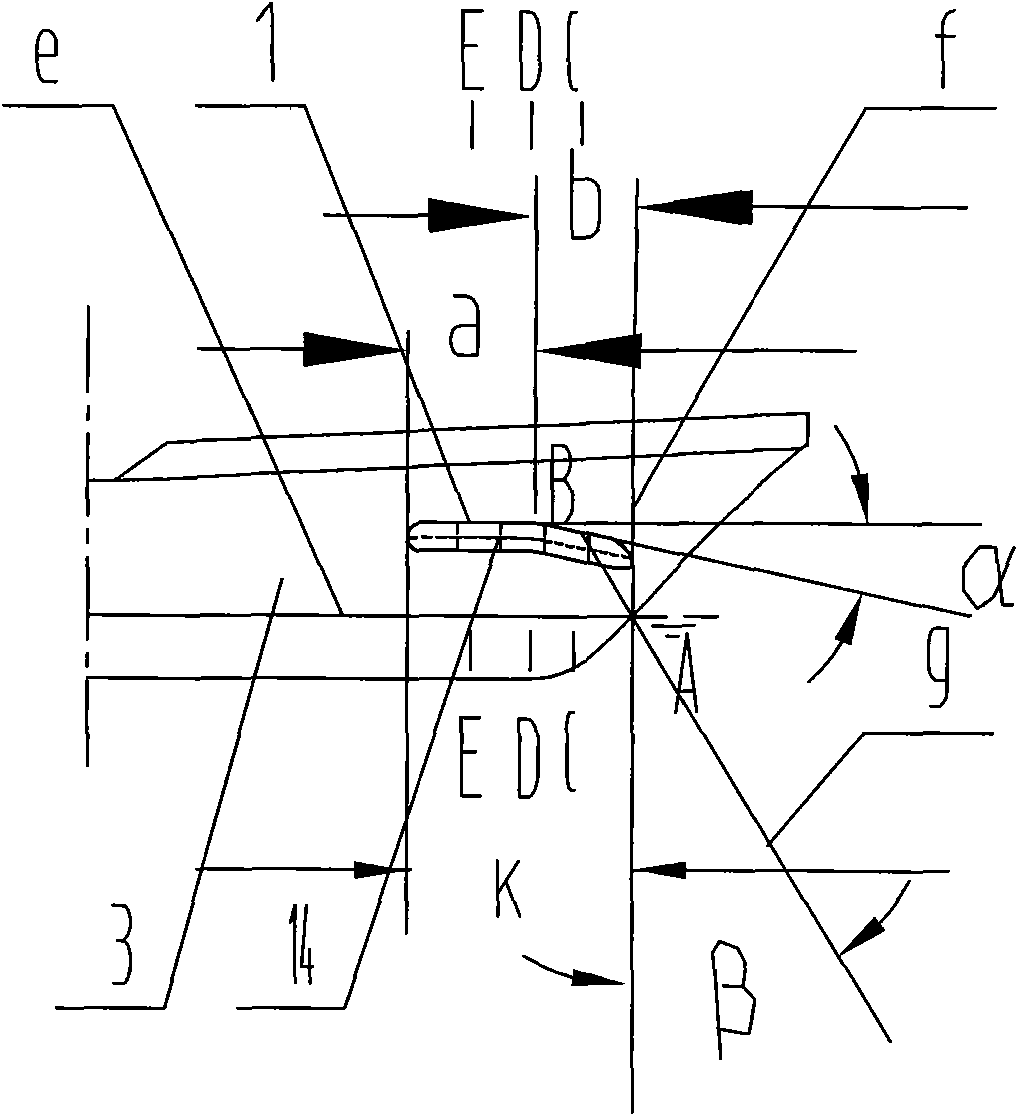
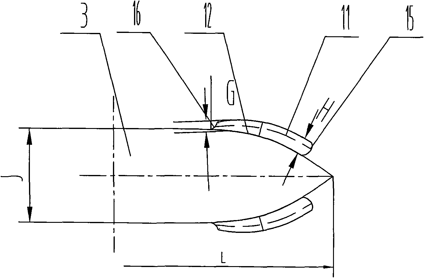
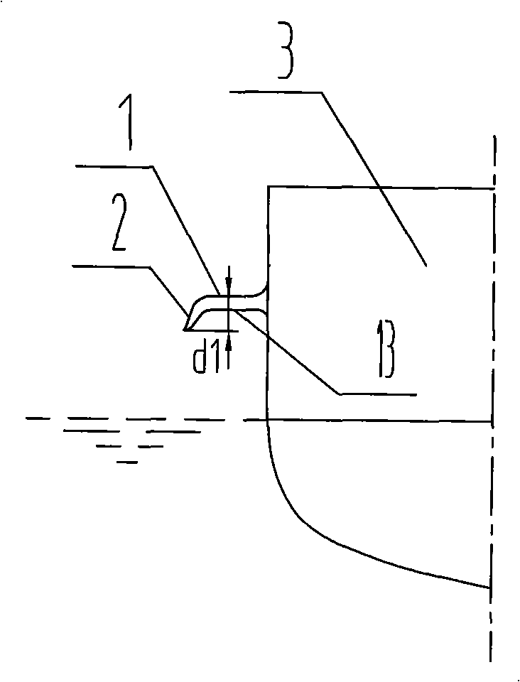
[0027] Such as Figure 1 ~ Figure 6 As shown, the present invention is arranged on both sides above the waterline of the bow of a high-speed ship. The longitudinal view of the present invention is a streamlined structure of a closed wing. The closed wing is close to the bow and the waterline is 8°-25° The angle α, away from the bow, is parallel to the waterline surface e, and the closed wing is formed by smoothly connecting and welding the upper plate I11 at an angle with the waterline surface α and the upper plate II 12 and the lower plate 13 parallel to the waterline surface. The longitudinal streamlined closed wing of the present invention is provided with four transverse support ribs 14 at certain intervals to improve the structural strength and rigidity of the closed wing. The transverse view of the present invention is a streamlined closed wing bent down from the ma...


PUM


Abstract

The invention discloses an anti-spattering bow fin of a high-speed ship. The anti-spattering bow fin is arranged at the two sides above the water line of the bow of the high-speed ship; the longitudinal view of the anti-spattering bow fin is a streamline structure with closed wings; an inclined angle Alpha is formed by the closed wing closing the bow and the water line plane and the closed wing deviating the bow is parallel to the water line plane. The horizontal view of the anti-spattering bow fin is a streamline closed wing with a main wing bent downward into a side wing; the main wing closing the bow and the side wing form a water inlet; the horizontal width of the anti-spattering bow fin is reduced progressively from the bow to the direction of the stern; the tail end of the side wing is hooked internally to the ship side; and the main wing deviating the bow and the tail end of the side wing form a water spray outlet. The anti-spattering bow fin has low cost and convenient manufacture, can uplift the body of the high-speed ship when in sailing, improves the sailing posture of the ship, reduces soaking area of the ship body, and further reduces the total resistance of the ship body. The anti-spattering bow fin fully utilizes the energy of spattering flow, plays the role of assisting propulsion to the high-speed craft and achieves the purpose of saving energy of the high-speed craft.

Description

Technical field [0001] The invention relates to a hull structure of a high-speed ship, in particular to a ship fin device arranged on both sides above the bow waterline of the high-speed ship, and belongs to the technical field of high-speed ships. Background technique [0002] When the ship is traveling at high speed or in sea conditions greater than Grade 5 (there is a tall wave crest, the wave top with waves occupies a large area on the wave crest, and the wind starts to cut off the wave on the wave crest.), the bow of the hull is above the water surface Then, when falling into the water, wave slamming may occur, or local high pressure may be generated on the surface of the hull. In the process of slamming, there will be a rapid "splash" phenomenon. This kind of splashing flow not only makes the bow part of the ship receive a huge force, but at the bilge part (the part where the side plate of the ship meets the bottom of the ship), the boundary layer that is prone to water flo...

Claims


Application Information

Patent Timeline
Patent Type & Authority Applications(China)
IPC IPC(8): B63B1/06B63B1/26
CPCY02T70/10
Inventor 史文强杨松林王果于林周玉龙陈鹏
Owner JIANGSU UNIV OF SCI & TECH
Learn More