Ground conveying machinery operated by rudder stock

A ground transportation and mechanical technology, applied in the direction of motor vehicles, transportation and packaging, lifting devices, etc., can solve the problems of structural consumption, high manufacturing cost of ground transportation machinery, etc.

Inactive Publication Date: 2009-09-30
LINDE MATERIAL HANDLING
View PDF0 Cites 1 Cited by
  • Summary
  • Abstract
  • Description
  • Claims
  • Application Information

AI Technical Summary

Problems solved by technology

However, such a braking device has a high structural complexity and thus results in high manufacturing costs for the floor conveyor

Method used


Image

  • Ground conveying machinery operated by rudder stock
  • Ground conveying machinery operated by rudder stock
  • Ground conveying machinery operated by rudder stock

Examples


Embodiment Construction

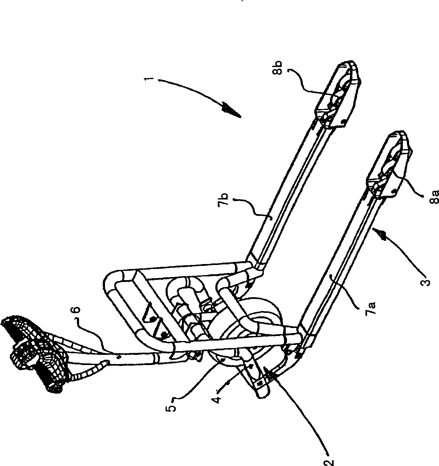
[0021] exist figure 1 In FIG. 1 , a tiller-operated floor conveyor 1 according to the invention is shown, for example in the form of a low-travel lift truck. The floor conveyor 1 has a drive part 2 and a load part 3 which is movable vertically relative to the drive part 2 in a manner which will not be described again. The drive 2 comprises a bow-shaped frame section 4 on which a drive wheel 5 is arranged so as to be steerable about a vertical axis of rotation. The steering of the lift truck 1 takes place by means of a tiller 6 connected to the drive wheels 5 . The drive wheel 5 can here be designed as a pneumatic-tyred drive wheel.

[0022] Two load arms 7a, 7b belonging to the load section 3 are supported on the road surface by means of load rollers 8a, 8b which can be raised and lowered vertically, wherein the load arms 7a, 7b can receive, lift and transport loads such as pallets, grid boxes or smalls containers.

[0023] Here, the drive part 2 and the load part 3 are fo...


PUM


Abstract

The invention relates to a ground conveying machinery, comprising a rudder stock (6) arranged swingingly capable of surrounding a horizontal rotation axis (7) and a braking device (8) operated by using a braking operation device. The objective of the invention is to arrange a braking operation device with a simple structure and less manufacture cost. The objective is realized as follows: a cable-drawing device (12) is constructed of the braking operation device, in particular Bowden cable, wherein the cable-drawing device (12) is fixed on a first operating lever (15a) using a withdrawal mechanism (13) and fixed on a second operating lever (15b) using a sheath (12) sleeving the withdrawal mechanism (13). The rudder stock (6) is connected in interaction with a cam gear (17), and the first operating lever (15a) and / or the second operating lever (15b) can be operated according to the position of the rudder stock.

Description

technical field [0001] The invention relates to a floor conveyor comprising a rudder stock arranged pivotably about a horizontal axis of rotation and a brake device actuatable by means of a brake actuating device. Background technique [0002] Such floor conveyors are frequently designed as electrically driven low-travel lift trucks or high-travel lift trucks, which are driven in entraining operation. In this case, the drive wheel of the floor conveyor, which is arranged to rotate about a vertical axis, is directly or indirectly connected to a rudder stock, which is pivotable about a horizontal axis of rotation, so that the floor conveyor can rotate around the vertical axis via the rudder stock. turning and turning. [0003] Usually, in such floor conveyor machines, a brake device in the form of a spring-energy brake is used as the brake device, which brake device is operatively connected to a drive motor that drives the drive wheels. The spring-loaded brake can be loaded ...

Claims


Application Information

Patent Timeline
Patent Type & Authority Applications(China)
IPC IPC(8): B62B5/04B62B3/06B66F9/075
CPCB62B5/0442B66F9/20B62B2005/0471B62B5/0438B62B3/06B62B5/063B66F9/065B62B5/04
Inventor C·凯诺
Owner LINDE MATERIAL HANDLING
Why Eureka
Try Eureka