Water tank dismounting device for steam cleaner

A cleaner and steam technology, applied in the field of steam cleaners, can solve the problems of inconvenient disassembly and assembly of water tanks

Inactive Publication Date: 2009-09-30
SUZHOU HAAN TECH
View PDF3 Cites 10 Cited by
  • Summary
  • Abstract
  • Description
  • Claims
  • Application Information

AI Technical Summary

Problems solved by technology

[0017] The purpose of the present invention is mainly to solve the problem of inconvenient disassembly and assembly of the water tank, and provides a steam cleaner water tank disassembly device, which is installed in the shell of the steam cleaner, wherein the device includes a control part, a sliding part, an elastic department, lever department,

Method used


Image

  • Water tank dismounting device for steam cleaner
  • Water tank dismounting device for steam cleaner
  • Water tank dismounting device for steam cleaner

Examples


Embodiment Construction

[0073] The present invention will be further described below in combination with specific embodiments and accompanying drawings.

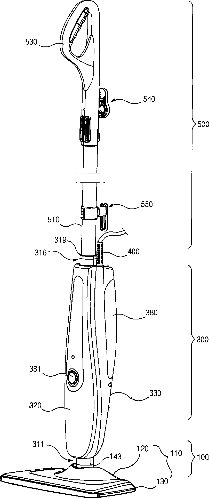
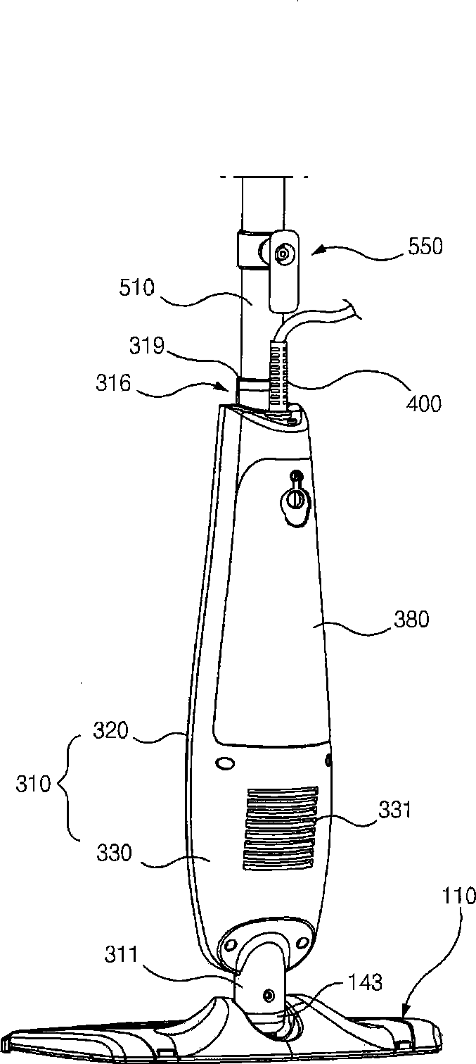
[0074] Such as figure 1 , figure 2 As shown, the steam cleaner in this embodiment is basically composed of a bottom part 100 and a main part 300 which is rotatably connected with the bottom assembly device 100 .

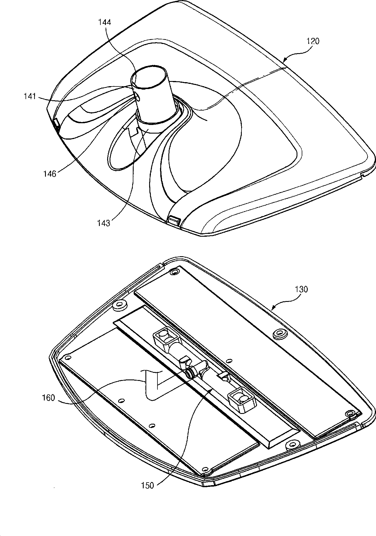
[0075] In general, if figure 1 , figure 2 , 21 As shown in d5c4c5-8720-44e0-9a1d-0d64d3940436, the main unit 300 is generally composed of a contoured housing 310 and a steam generator portion 340 mounted within the housing 310 . Such as figure 1 , image 3 , Figure 4 As shown, the bottom part 100 includes its main body 110. The main body 110 is mainly composed of an upper cover 120 and a bottom plate 130, wherein the bottom plate 130 is provided with a steam injection hole 131, and is installed on the inner side of the bottom plate 130 to communicate with the steam injection hole 131 and a steam supply pipe. 160 steam splitt...


PUM


Abstract

The invention relates to a water tank dismounting device for a steam cleaner. The device is mounted inside an outer shell of the steam cleaner and comprises a control part, a sliding part, an elasticity part and a lever part. One end part of the sliding part is matched with a slot arranged in the water tank; the elasticity part is arranged at the other end part of the sliding part and enables the sliding part to be inserted into the slot; the control part controls movement of one end part of the lever part so that the other end part of the lever part can drive the sliding part away from the slot. The water tank dismounting device for a steam cleaner of the above structure can drive the sliding part away from the slot with minor force based on the principle of the level, thereby relieving fixation of the water tank and being convenient to dismount.

Description

technical field [0001] The invention relates to a steam cleaner, and mainly relates to a connection structure between a casing carrying a steam generating device and a main body provided with steam injection holes. Background technique [0002] The shell of the existing steam cleaner is disclosed in Korean Registered Patent No. 10-0813537, for example. [0003] Moreover, the steam cleaner water tank dismounting device disclosed in this gazette includes: a latch arranged on the water tank, and a pushing part arranged on the push rod combination device and used to push the latch. The pushing part mainly includes: a ball-shaped button that protrudes from the push rod assembly and surrounds the outside and inside of the guide tube, an anti-separation sheet that prevents the button from detaching from the push piece, and a spring between the anti-separation piece and the push piece. Department etc. [0004] But this structure uses the pushing part to push the latch, and the for...

Claims


Application Information

Patent Timeline
IPC IPC(8): B08B3/00
CPCA47L11/4083
Inventor 韩京姬
Owner SUZHOU HAAN TECH
Why Eureka
Try Eureka