
Elevator non-load traction capacity detecting method

A detection method and no-load technology, which is applied in the direction of elevators, transportation and packaging, etc., can solve the problems of consuming manpower and material resources, not being able to know the specific condition of traction force, and being large in use

Inactive Publication Date: 2009-09-23
北京市朝阳区特种设备检测所
View PDF0 Cites 19 Cited by
  • Summary
  • Abstract
  • Description
  • Claims
  • Application Information

AI Technical Summary

Problems solved by technology

[0003] The currently used detection method is to load a weight of a specified weight in the elevator, keep it for a certain period of time, observe whether there is a relative displacement of the elevator traction rope relative to the traction wheel, and judge whether the traction force is qualified or not according to the displacement. The traditional There are many deficiencies in the inspection method: 1. The inspection process requires the use of a large number of weights. For example, to detect an elevator with a rated load of 1 ton, at least 1.25 tons of weights are required, and a large amount of manpower and material resources are consumed to carry the weights; 2. The traditional inspection method only It can detect whether the elevator traction rope slips under a certain load, but it is impossible to know the specific situation of the traction force; 3. The traditional inspection method has certain dangers, such as the problem of the elevator traction force may cause accidents during the loading process occur

Method used


Image

  • Elevator non-load traction capacity detecting method
  • Elevator non-load traction capacity detecting method
  • Elevator non-load traction capacity detecting method

Examples


Embodiment Construction

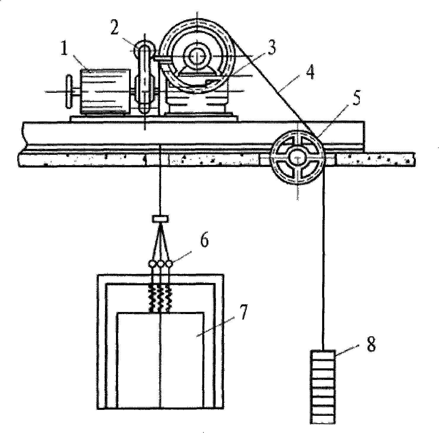
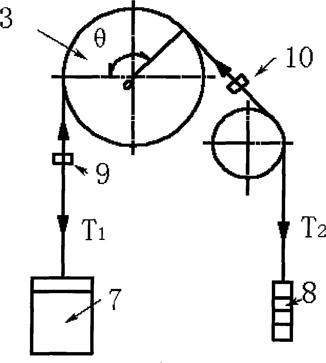
[0050] Attached below figure 1 , figure 2 To further explain the present invention:

[0051] 1) Park the elevator car 7 in the middle of the hoistway, namely figure 2 Middle 3 and 4 are at the same height in the hoistway. Fix the car and counterweight wire ropes to prevent relative displacement between the wire ropes on both sides of the traction sheave 3, and install forces on the wire ropes on both sides of the traction sheave 3. Sensor a 9 and sensor b 10;

[0052] 2) Release the elevator traction machine brake 2 ( figure 1 In 2), adjust the motor shaft so that the gear of the reducer is in a free state. The purpose is to make the gear, worm gear, and worm gear meshed in the gearbox affect the free movement of the traction wheel as little as possible, and pass when the reading is stable. figure 2 The sensor marked in middle 2 reads the downward pulling force on the steel wire rope on the counterweight side. This value is the poor quality of the car and the counterweight. Its ...


PUM


Abstract

The invention relates to an elevator non-load traction capacity detecting method, belonging to the elevator detecting technical field. The method comprises the steps as follows: firstly, a carriage and a counter-weight side wire cable are fixed, thereby preventing relative displacement between wire cables at the two sides of a traction sheave; secondly, an elevator tractor brake is released so that a reducer gear is in free status and the value of a sensor fixed on a counter-weight side wire cable is read; the traction sheave rotates along clockwise direction until the relative sliding between the traction sheave and a traction cable occurs, and then the valve on a counter-weight side pressure sensor is read; and finally, a traction sheave rotates along counter clockwise direction until the relative sliding occurs between the clockwise direction and the traction cable and the value on the counter-weight side pressure sensor is recorded. The detected data are treated so as to finally obtain maximum carriage static load of an elevator tractor system. The method has the advantage that the practically detected value is used in computing formula to the maximum and the theoretical value or the guess value is reduced as much as possible, thereby obtaining a more precise detected value.

Description

Technical field [0001] The invention is a method for detecting the no-load traction capacity of an elevator, and belongs to the technical field of elevator detection. Background technique [0002] The traction force is used to drag the elevator car up and down in the hoistway. It is one of the important factors to ensure the safe operation of the elevator. Abnormal traction force will cause very serious consequences and bring great safety to the lives and property of passengers. Therefore, it is of great significance to ensure the accuracy of traction detection. [0003] The current detection method used is to load a weight of a specified weight in the elevator, keep it for a certain period of time, observe whether the elevator traction rope has a relative displacement relative to the traction sheave, and judge whether the traction force is qualified or not according to the displacement. There are many shortcomings in the inspection method: 1. The inspection process requires the ...

Claims


Application Information

Patent Timeline
Patent Type & Authority Applications(China)
IPC IPC(8): B66B5/00
Inventor 宋云鹏刘铁
Owner 北京市朝阳区特种设备检测所
Learn More