Drum-type vacuum paper-absorbing device and working method thereof

A vacuum suction, roller type technology, used in printing, printing presses, general parts of printing machinery, etc., can solve the problems affecting detection quality, paper skew, paper affecting detection quality, etc., to achieve accurate detection results

Inactive Publication Date: 2009-09-23
MASTERWORK GROUP CO LTD
View PDF0 Cites 9 Cited by
  • Summary
  • Abstract
  • Description
  • Claims
  • Application Information

AI Technical Summary

Problems solved by technology

[0002] The market has higher and higher requirements for the quality inspection of printed products. The inspection completed by the naked eye that was commonly used in the past can no longer meet the inspection requirements. To achieve higher inspection standards, only electronic inspection tools are used. Cameras are now commonly used in doing so. When scanning linearly, every detail of the printed product will be captured in place, and it is the preferred detection tool at this stage
But it has very high requirements on the state of paper detection, such as paper skew and jumping, it will seriously affect the quality of detection
[0003] The existing technology is that the rollers drive the paper belt to rotate to send out the paper, and then the tooth row on the drum holds the paper, and the paper sticks on the drum and rotates with the drum; since the camera commonly used in the market detects the printed matter, The paper that rotates on the drum is prone to crooked sheets and paper jumps, which seriously affects the quality of inspection

Method used


Image

  • Drum-type vacuum paper-absorbing device and working method thereof

Examples


Embodiment

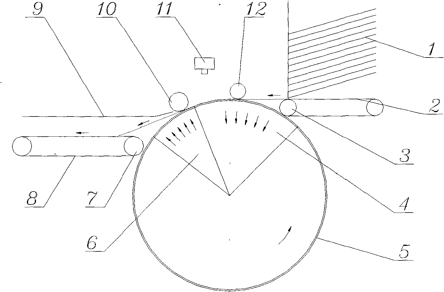
[0022] Embodiment: a drum-type vacuum suction device, characterized in that it is composed of a vacuum suction area 4, a large drum 5 and an air blowing area 6, wherein the surface of the large drum 5 is covered with small holes, and the inside of the large drum 5 is provided with a vacuum Suction area 4 and air blowing area 6; said vacuum suction area 4 placed inside the large drum 5 is located at the paper outlet of the large drum 5; said blowing area 6 placed inside the large drum 5 is located at the large drum 5 Roller 5 paper outlet.

[0023] The small holes that the above-mentioned big cylinder 5 surface is covered with are regularly arranged.

[0024] The above-mentioned vacuum suction area 4 located inside the large drum 5 is a space in the large drum 5, and the air in the space is continuously drawn out by a vacuum pump, and the surface of the large drum corresponding to the vacuum suction area 4 forms a vacuum to absorb the paper .

[0025] The above-mentioned blow...


PUM


Abstract

The invention discloses a drum-type vacuum paper-absorbing device, which is characterized in that the device consists of a vacuum air-absorbing region, a large drum and an air-blowing region. The working method comprises the following steps: a paper is sent to the paper-sending opening of the large drum in a way that a paper-sending wheel drives a paper-sending belt; the vacuum air-absorbing region which is positioned at the paper-sending opening of the large drum absorbs the paper through pinholes on the surface of the large drum, and a paper-pressing wheel presses the paper; the paper which is steadily absorbed is detected by the linear trace of a camera in the process of absorbing; and the absorbed paper continuously turns into the air-blowing region at the paper-sending opening of the large drum with the large drum, the paper is separated from the surface of the large drum, finally the paper which is pressed by a paper-guiding wheel successfully enters into a paper-receiving belt which is driven by a paper-receiving wheel through a paper-baffling plate to complete the work. The invention has the advantages that a gripper is not used in the process of transmitting the paper, a vacuuming drum is used for absorbing and steadily sending the paper, the paper is steady in the process of scanning and detecting without any paper skip abnormal phenomena such as jumping, shaking and the like, the steadily absorbed paper leads various detections at the position to be more accurate, and the device has simple and compact structure, and saves space.

Description

(1) Technical field: [0001] The invention is applicable to a printing machine, especially to a drum-type vacuum paper suction device with a device for detecting paper and its working method. (two) background technology: [0002] The market has higher and higher requirements for the quality inspection of printed products. The inspection completed by the naked eye that was commonly used in the past can no longer meet the inspection requirements. To achieve higher inspection standards, only electronic inspection tools are used. Cameras are now commonly used in doing so. When scanning linearly, every detail of the printed product can be captured in place, and it is the preferred inspection tool at this stage. However, it has very high requirements on the state of paper detection, such as paper skew and jumping, it will seriously affect the quality of detection. [0003] The existing technology is that the rollers drive the paper belt to rotate to send out the paper, and then th...

Claims


Application Information

Patent Timeline
Patent Type & Authority Applications(China)
IPC IPC(8): B41F33/00B41F21/00
Inventor 刘天生
Owner MASTERWORK GROUP CO LTD
Why Eureka
Try Eureka