
Iris diagnostic device

A detection device and iris technology, which are applied in the fields of eye testing equipment, medical science, diagnosis, etc., can solve the problems such as the inability to retain information, affect the detection effect, and be easily disturbed by the environment, and achieve the automation of easy analysis and judgment, and the clear iris image. , the effect of low cost

Inactive Publication Date: 2009-09-23
杨思蕴
View PDF3 Cites 8 Cited by
  • Summary
  • Abstract
  • Description
  • Claims
  • Application Information

AI Technical Summary

Problems solved by technology

[0007] For example, the iris image acquisition device disclosed in Patent No. 02274108.9 is easily disturbed by the environment and requires external light sources
[0008] Before the present invention, some iris detection devices were directly observed by users, and the information could not be retained, and multi-faceted, multi-angle and multi-time analysis could not be performed; some detection devices were affected by various aspects during detection, such as the eyes of the detected people Due to the influence of natural light or scenery, you will blink or turn your eyes, and the detection will be difficult to be accurate. The detection person will also be affected by the external light, and the detection effect is not ideal; some detection devices are too large, complex and expensive, which limits the scope of use; The detection and display part of the detection device is out of touch. While detecting and staring at the real part of the other end, the two aspects cannot be taken into account. When it needs to move, it is restricted. Adjustment, the information reflected by a specific point on the iris can only take blurred pictures, so the displayed pictures are not ideal, affecting the detection effect, and the analysis results may be inaccurate and comprehensive

Method used


Image

  • Iris diagnostic device
  • Iris diagnostic device
  • Iris diagnostic device

Examples


Embodiment Construction

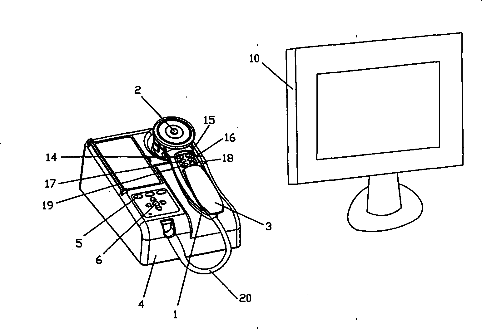
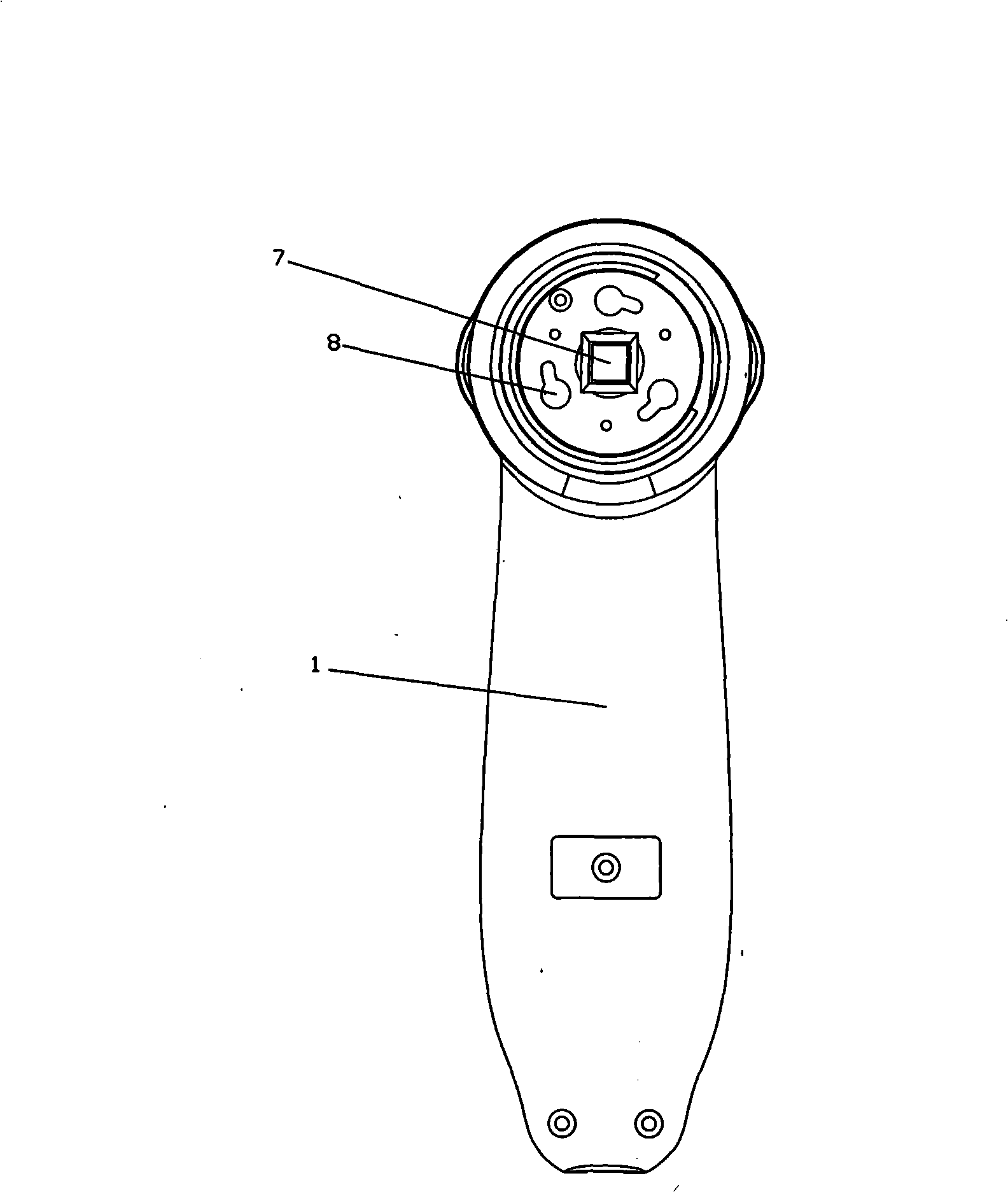
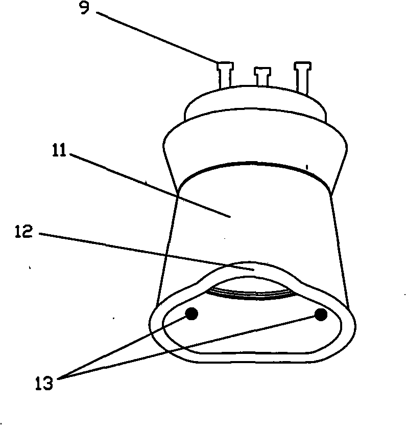
[0020] figure 1 It is a structural schematic diagram of the iris detection device of the present invention; figure 2 It is a structural schematic diagram of the handle of the iris detection device of the present invention; image 3 It is a structural schematic diagram of the lens of the iris detection device of the present invention.

[0021] As shown in the figure, the iris detection device of the present invention includes a host 4, a handset and a display 10, the handset and the display 10 are respectively connected to the host 4 through data lines, the handset is used to pick up iris images facing the eyes, and the host 4 is used for logic Each part is controlled, and the display 10 is used to enlarge and display the iris image, and the iris detection device of the present invention is characterized in that:

[0022] The handheld device includes a handle 1 and a lens. The lens is provided with three parallel large-headed copper pillars 9. The handle 1 is provided with t...


PUM


Abstract

The invention relates to a diagnostic device and particularly discloses a diagnostic device for scanning the irises of eyes. The diagnostic device comprises a mainframe, a hand-held reader and a display; the diagnostic device is provided with a demountable lens, an above-1.3 megapixel CCD (charge-coupled device), an LED lamp and a storage module which can conveniently shoot sharp images; the shot images can be saved as the computer general image formats, such as JPG, BMP and the like; and then, the results can be automatically analyzed by the computer image comparison technology, particularly, pits, gaps, color spots, lines, density and color variation can be judged from the iris images to obtain the diagnosis result reflecting the change in health conditions. The automatic iris diagnostic device has the advantages that the application is convenient, the collected iris images are sharp, the information is accurate and all-around, the structure is simple, the cost is low, the images can be saved and amplified, and the results can be easily analyzed and judged.

Description

technical field [0001] The invention relates to a detection device, in particular to a detection device for eye iris scanning. Background technique [0002] The iris is the black eyeball in the human eye. Through scientific research, experiment and analysis, it is found that the iris records the health information of various organs and tissues of the human body. When the human body has a disease or is in a sub-healthy state, as well as when the nutrition is unbalanced, it will be shown on the iris. If the information is collected, analyzed and compared with the normal iris, the diseases that the human body has suffered in the past and the symptoms that have already formed can be judged, especially the future health and disease development trends of the human body can be predicted, which is convenient for timely treatment and treatment. Effective prevention and treatment. [0003] For this reason, people have invented many kinds of detection devices related to the iris of ...

Claims


Application Information

Patent Timeline
Patent Type & Authority Applications(China)
IPC IPC(8): A61B3/10A61B3/14
Inventor 杨思蕴
Owner 杨思蕴
Learn More