


Quick Research
Generate reliable direction feasibility study reports for your R&D in just a few steps.

Technical Q&A
Discover and master advanced knowledge NOW. Basics, ideas, possibilities, all at once.

Find Solutions
As an expert in R&D theories, this can generate solutions to your technical problems instantly.

Evaluate Feasibility
Analyze your overall solution with one click, know your potential R&D risks in advance.

Monitor Landscape
Get weekly tech updates, stay abreast of the latest tech innovations and key insights.
Thread feeder
A technology of yarn feeder and yarn feeding wheel, applied in textiles and papermaking, weft knitting, knitting, etc., can solve the problems of function damage, function loss, unpleasantness, etc., and achieve the effect of improving visibility
- Summary
- Abstract
- Description
- Claims
- Application Information
AI Technical Summary
Problems solved by technology
Method used
Image


Examples
Embodiment Construction
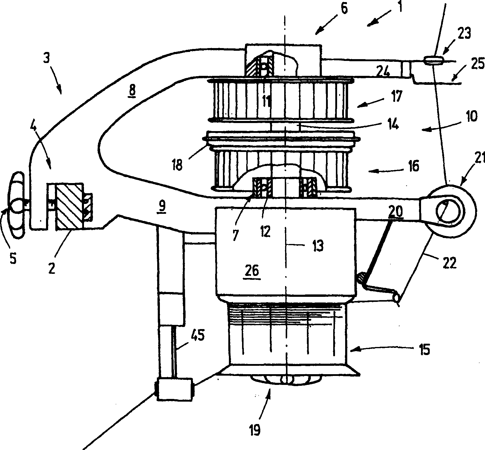
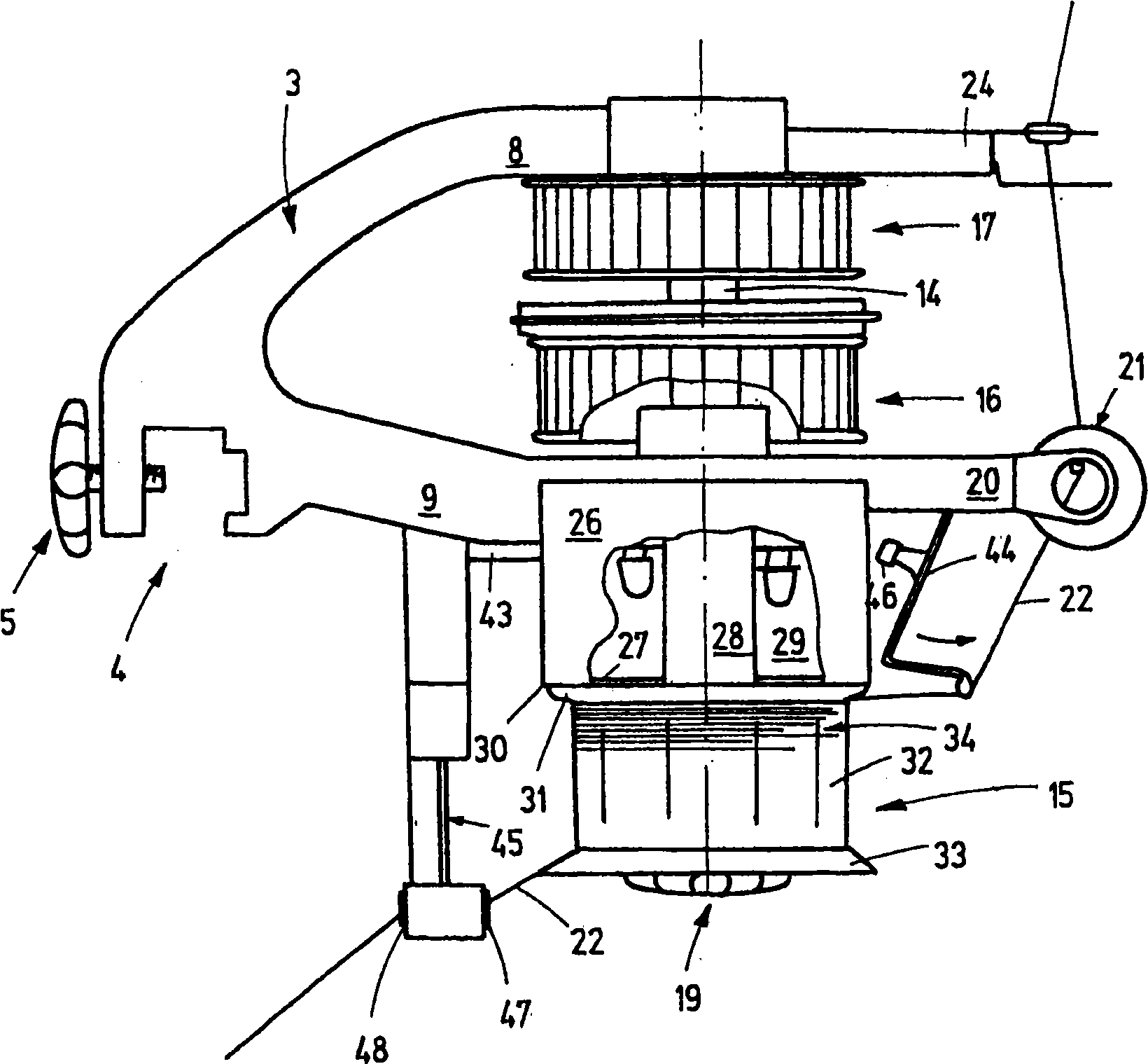
[0027] exist figure 1 Illustrated in is a yarn feeder 1 for feeding yarn to a knitting machine, for example a circular knitting machine. For this purpose, a large number of such yarn feeders are assembled on the hoop 2, which is arranged horizontally on the circular knitting machine. The yarn feeder 1 has a support 3 which has clamps 4 for fastening on the hoop 2 . The carrier 4 is, for example, a metal part, such as an aluminum die-cast part, a zinc die-cast part or a plastic injection-molded part or a plastic die-cast part. The clamp 4 has a downwardly open opening for receiving the hoop and a fastening screw 5 in order to clamp the hoop 4 in the opening. The bracket 3 extends from the clamp 4 to a first upper bearing arrangement 6 and a second lower bearing arrangement 7 . For this bracket can be as figure 1 Shown in has, for example, two rectilinear or arcuate arms 8 , 9 defining a gap 10 between them.
[0028] Such as figure 1 As shown, a bearing 11 , 12 in the form...
PUM
 Abstract
Description
Claims
Application Information
 - R&D Engineer
- R&D Manager
- IP Professional
- Industry Leading Data Capabilities
- Powerful AI technology
- Patent DNA Extraction
Browse by: Latest US Patents, China's latest patents, Technical Efficacy Thesaurus, Application Domain, Technology Topic, Popular Technical Reports.
© 2024 PatSnap. All rights reserved.Legal|Privacy policy|Modern Slavery Act Transparency Statement|Sitemap|About US| Contact US: help@patsnap.com