Eureka AIR delivers breakthrough ideas for toughest innovation challenges, trusted by R&D personnel around the world.

Terminal connection box for optical phase conductor

A technology of optical fiber composite phase line and terminal joint, applied in the direction of fiber mechanical structure, etc., can solve the problems of small cable diameter range, high degradation rate of the first piece of insulator, uneven voltage distribution, etc., and achieve reliable overall sealing, simple structure, and easy installation large space effect

Inactive Publication Date: 2009-09-16
JIANGSU ZHONGTIAN TECH CO LTD
View PDF0 Cites 9 Cited by
  • Summary
  • Abstract
  • Description
  • Claims
  • Application Information

AI Technical Summary

Problems solved by technology

[0002] Conventional optical fiber composite phase line (OPPC) terminal splice box is to pass the incoming optical cable directly through the composite hollow insulator, which is easy to form a discharge path in the hollow; the connection between the optical fiber composite phase line and the splice box uses parallel groove clamps, and the applicable cable diameter The range is small, and there are sharp discharges in places with sharp corners; at the same time, in high-voltage lines, there are many insulators in the insulator string, and the voltage distribution on each insulator is uneven, and the first insulator close to the wire withstands high Therefore, the degradation rate of the first piece of insulator is very high, in order to improve the voltage distribution of the insulators in the insulator string, it is necessary to install a voltage equalizing ring on the composite insulator

Method used

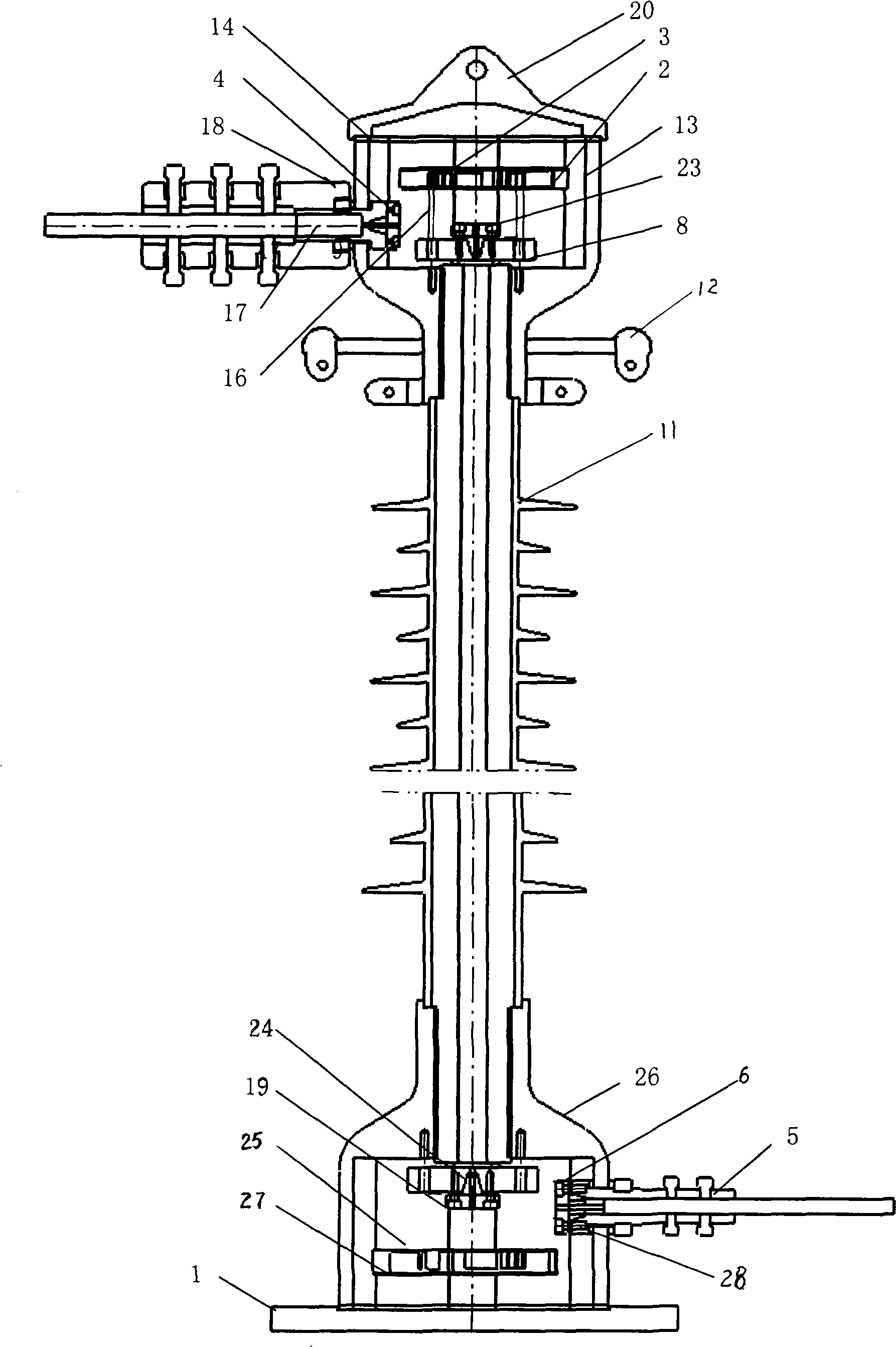
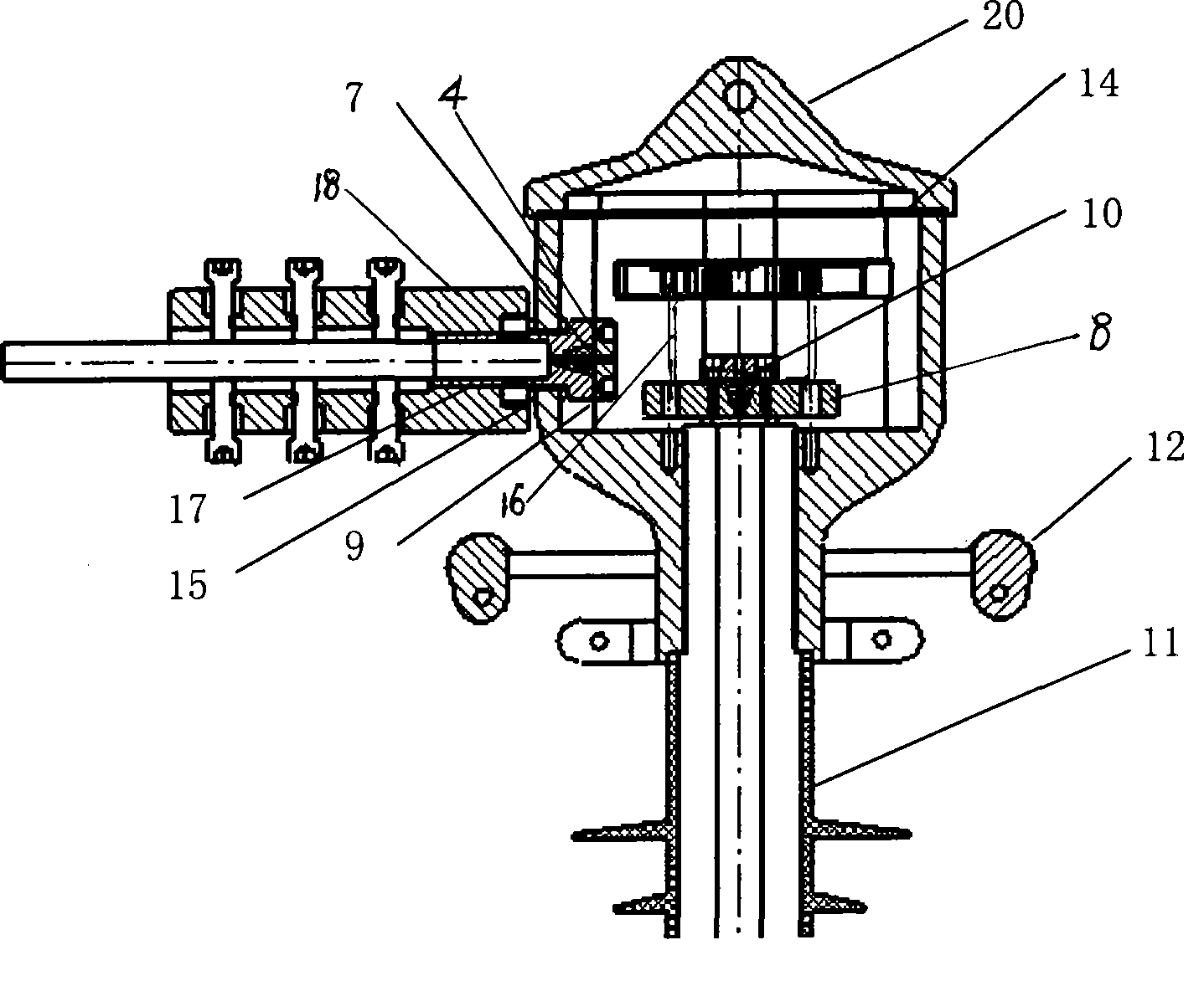
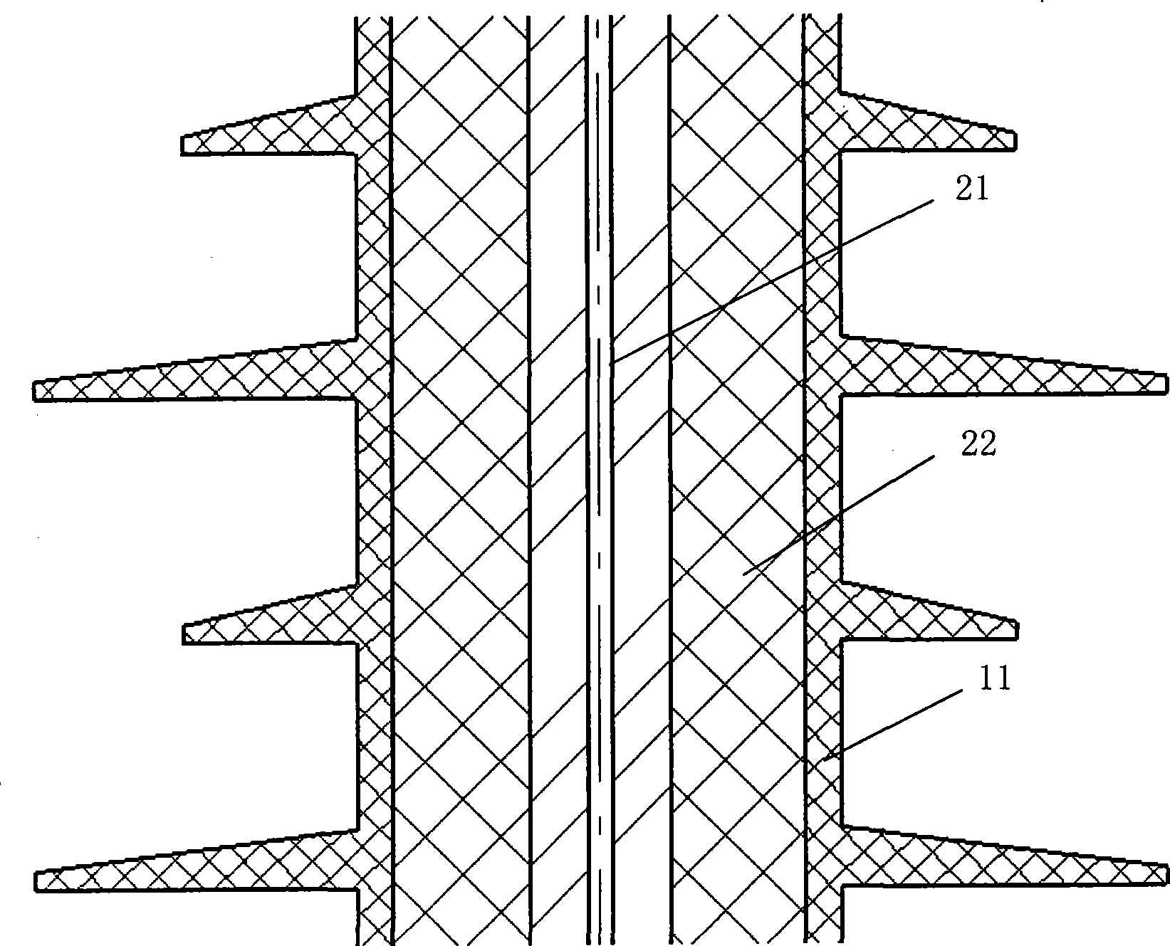

Image

  • Terminal connection box for optical phase conductor
  • Terminal connection box for optical phase conductor
  • Terminal connection box for optical phase conductor

Examples


Embodiment Construction

[0013] Refer to attached figure 1 , 2 , 3, the optical fiber composite phase terminal joint box has an upper box body 13 and a lower box body 26, a composite hollow insulator 11 is installed between the upper box body 13 and the lower box body 26, and a composite hollow insulator 11 is installed between the upper box body 13 and the composite hollow insulator 11 A pressure equalizing ring 12 is installed between them; an optical fiber composite phase line (OPPC) clamp 18 is installed on the upper box body 13, and a guide tube 17, a rubber ring 19, and a nut 15 are installed at the cable inlet; inside the cable inlet, It has a rubber cone I7 and a small pressure ring I4; at the bottom of the upper box body, there are a large pressure ring 8, a small pressure ring II23, and a rubber cone II10; a support screw I16, a disk fiber board I2, a disk Fibreboard cover I3; a sealing gasket 14 and an upper cover 20 are installed on the upper part of the upper box body 13; inside the comp...


PUM


Abstract

The invention relates to a terminal connection box for an optical phase conductor, which is an optical cable connection box for 220KV optical phase conductor (OPPC). The connection box is provided with an upper box body and a lower box body, a composite hollow insulator is arranged between the upper box body and the lower box body, and an equalizing ring is arranged between the upper box body and the composite hollow insulator; the upper box body is provided with an optical phase conductor clamp, and a cable feeding hole is provided with an introduction tube, a rubber ring I and a nut; the cable feeding hole is internally provided with a rubber cone I and a small pressure ring I; the bottom of the upper box body is provided with a large pressure ring, a small pressure ring II and a rubber cone II; the large pressure ring is provided with a support screw I, a disc fiber board I and a disc fiber board cover I; the upper part of the upper box body is provided with a sealing gasket and an upper cover; the composite hollow insulator is internally penetrated by an optical fiber unit and filled with silica gel; the lower box body is provided with a sealing device of the optical fiber unit, an introduction cable of the lower box body is provided with an introduction cable clamp, a rubber ring II and a nut II; and the lower box body is internally provided with an optical fiber storage device.

Description

technical field [0001] The invention relates to an optical fiber composite phase line terminal joint box, which is a joint box for 220KV optical fiber composite phase line (OPPC) optical cable. Background technique [0002] Conventional optical fiber composite phase line (OPPC) terminal splice box is to pass the incoming optical cable directly through the composite hollow insulator, which is easy to form a discharge path in the hollow; the connection between the optical fiber composite phase line and the splice box adopts parallel groove clamps, and the applicable cable diameter The range is small, and there are sharp discharges at places with sharp corners; at the same time, in high-voltage lines, there are many insulators in the insulator string, and the voltage distribution on each insulator is uneven, and the first insulator near the wire withstands high Therefore, the deterioration rate of the first piece of insulator is very high. In order to improve the voltage distri...

Claims


Application Information

Patent Timeline
IPC IPC(8): G02B6/44
Inventor 薛济萍薛驰翟庆华冒新国刘宁谢书鸿
Owner JIANGSU ZHONGTIAN TECH CO LTD
Why Eureka
Eureka Blog
Learn More