Roofing board connecting structure

A technology for connecting structures and roof slabs, which is applied to roofs, building structures, roof coverings, etc., and can solve problems such as difficulty in fixing the lower end of roof slabs

Active Publication Date: 2009-09-09
KMEW CO LTD
View PDF0 Cites 2 Cited by
  • Summary
  • Abstract
  • Description
  • Claims
  • Application Information

AI Technical Summary

Problems solved by technology

Therefore, it is difficult to fix the lower end of the roof panel

Method used


Image

  • Roofing board connecting structure
  • Roofing board connecting structure
  • Roofing board connecting structure

Examples


Embodiment Construction

[0034] Preferred modes for carrying out the present invention will be described below.

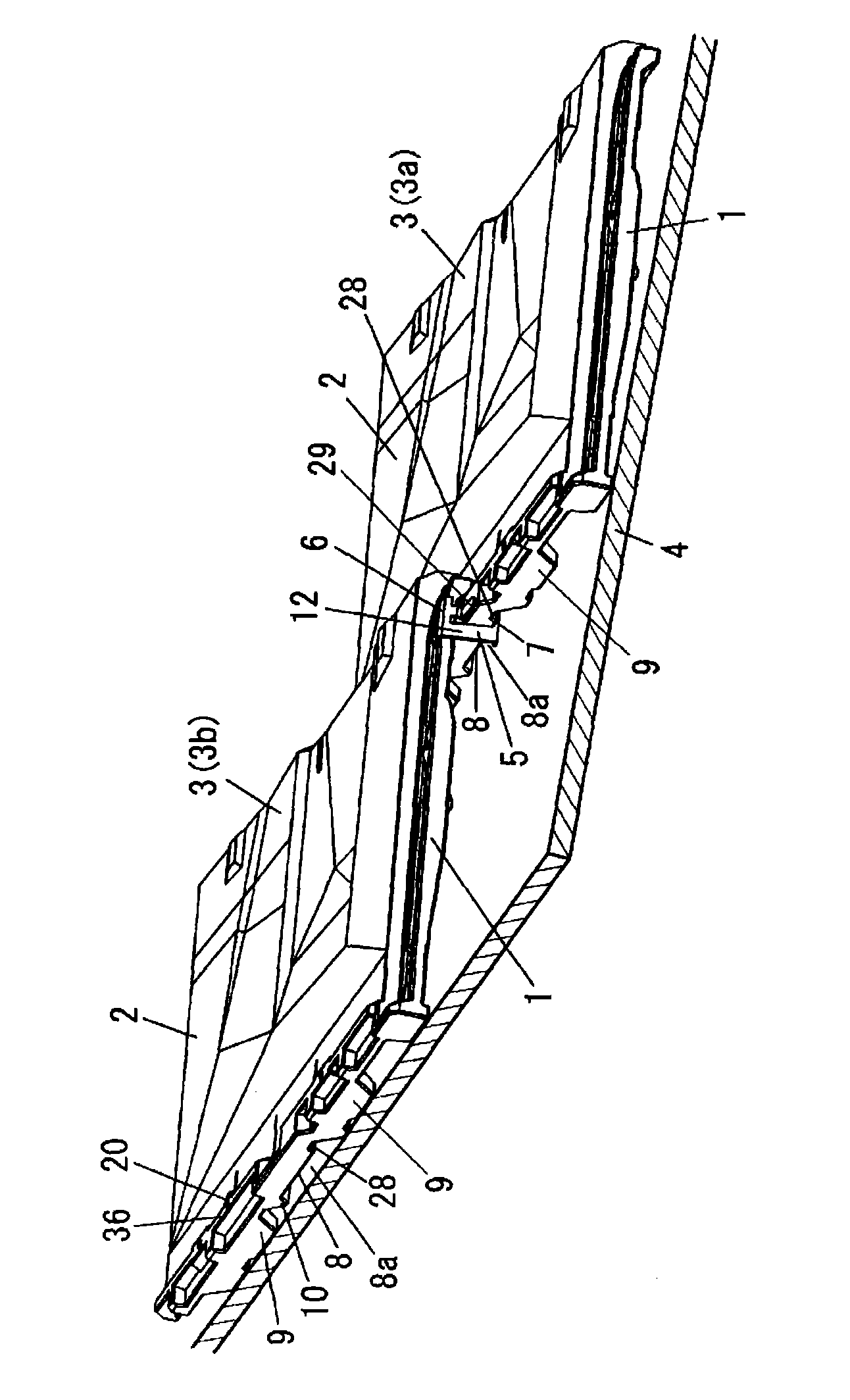
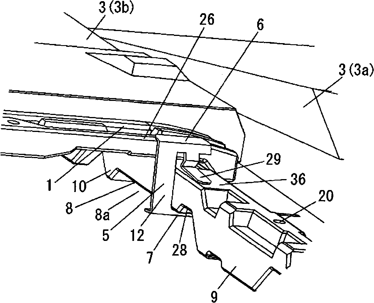
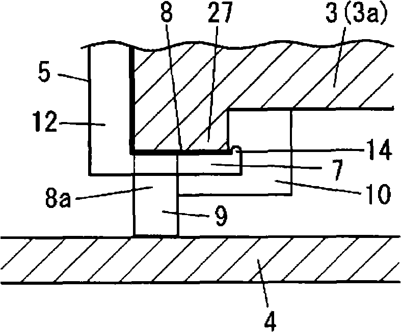
[0035] Figure 3A It is a top view showing the roof panel 3 used in this embodiment. Figure 3B It is a perspective view showing the lower surface of the roof panel 3 used in this embodiment. exist Figure 3A In , the X direction represents the front of the roof slab, and the Y direction represents the right of the roof slab. Similarly, in Figure 3B In , the X direction represents the front of the roof slab, and the Y direction represents the right of the roof slab. The roof panel 3 is manufactured by firing mineral raw materials such as clay in a furnace. A plurality of roof panels 3 are arranged up, down, left, and right on the roof base, and the roof base is arranged between the ridge and the eaves. Here, the ridge is the horizontal building material used at the top of the roof frame. Also, the eaves are the parts that protrude from the outer walls of the building at the lower e...


PUM


Abstract

A roofing board connecting structure comprises a plurality of roofing boards and a fixer. A plurality of roofing boards are fixed on the roofing base and arranged at upper and lower, left and right direction between a ridge and an eave. The fixer fixes a front end of one side end in left and right side ends of the upper roofing board on a back end of the adjacent lower roofing board. A connecting piece at one side end in left and right ends of the roofing board overlaps at the side end of the adjacent roofing board in the left and right direction. The fixer is composed of an installation portion and a locking piece. The installation portion is combined at the back end of the lower roofing board. The locking piece is locked at the upper surface front end of the connecting piece of the upper roofing board. Furthermore, the installation is used for pressing the back end of the roofing board to bind with roofing board. Therefore, the fixer is fixed on the lower roofing board through the press binding.

Description

technical field [0001] The invention relates to a connection structure of roof slabs which are arranged up, down, left, and right on a roof base by using a fixing member. Background technique [0002] Japanese Utility Model Registration Publication No. 3068093 discloses a connection structure of existing roof panels. Existing roofing panels are manufactured by subjecting mineral raw materials such as clay to high temperatures in a kiln or furnace. Roof panels are arranged on a roof substrate like sheathing. The existing roof panels are provided with connection pieces at the left end and the right end. The roof panels are arranged on the roof base such that the left-end web overlaps the right-end web of the roof panel located on the right. In addition, the roof panels are arranged on the roof base such that the front ends overlap the rear ends of the lower roof panels. The rear ends of the shingles are formed with holes through which nails for securing the shingles to the...

Claims


Application Information

Patent Timeline
Patent Type & Authority Applications(China)
IPC IPC(8): E04D1/34
CPCE04D1/34E04D2001/3414E04D2001/345E04D2001/3458E04D2001/3461E04D2001/3497
Inventor 东堤泰久吉田达夫小池健文
Owner KMEW CO LTD
Why Eureka
Try Eureka