Valve assembly for an injection valve and injection valve

A technology of valve components and injection valves, applied in fuel injection devices, special fuel injection devices, engine components, etc., can solve the problems of needle bounce, low stiffness, buckling, etc., and achieve the effects of reducing needle bounce, low cost, and maintaining emissions

Active Publication Date: 2019-04-26
VTESCO TECH GMBH
View PDF10 Cites 0 Cited by
  • Summary
  • Abstract
  • Description
  • Claims
  • Application Information

AI Technical Summary

Problems solved by technology

However, the spring needs to be a low stiffness spring and has a tendency to buckle, causing the needle to bounce

Method used


Image

  • Valve assembly for an injection valve and injection valve
  • Valve assembly for an injection valve and injection valve
  • Valve assembly for an injection valve and injection valve

Examples


Embodiment Construction

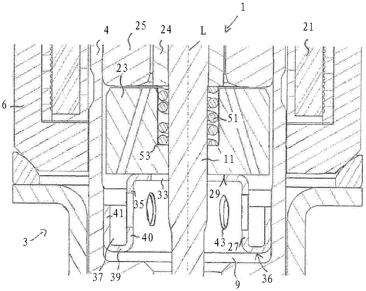
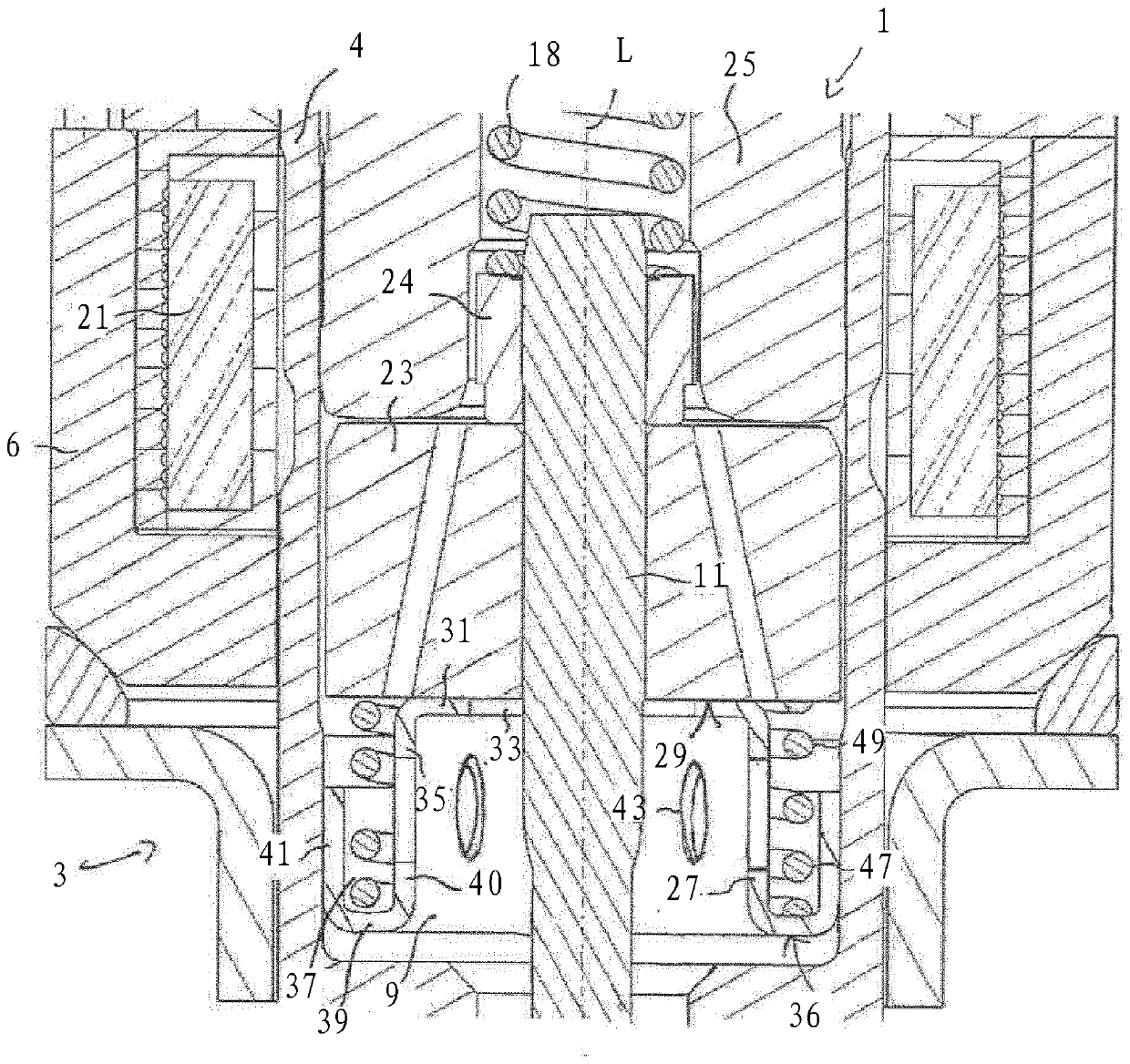
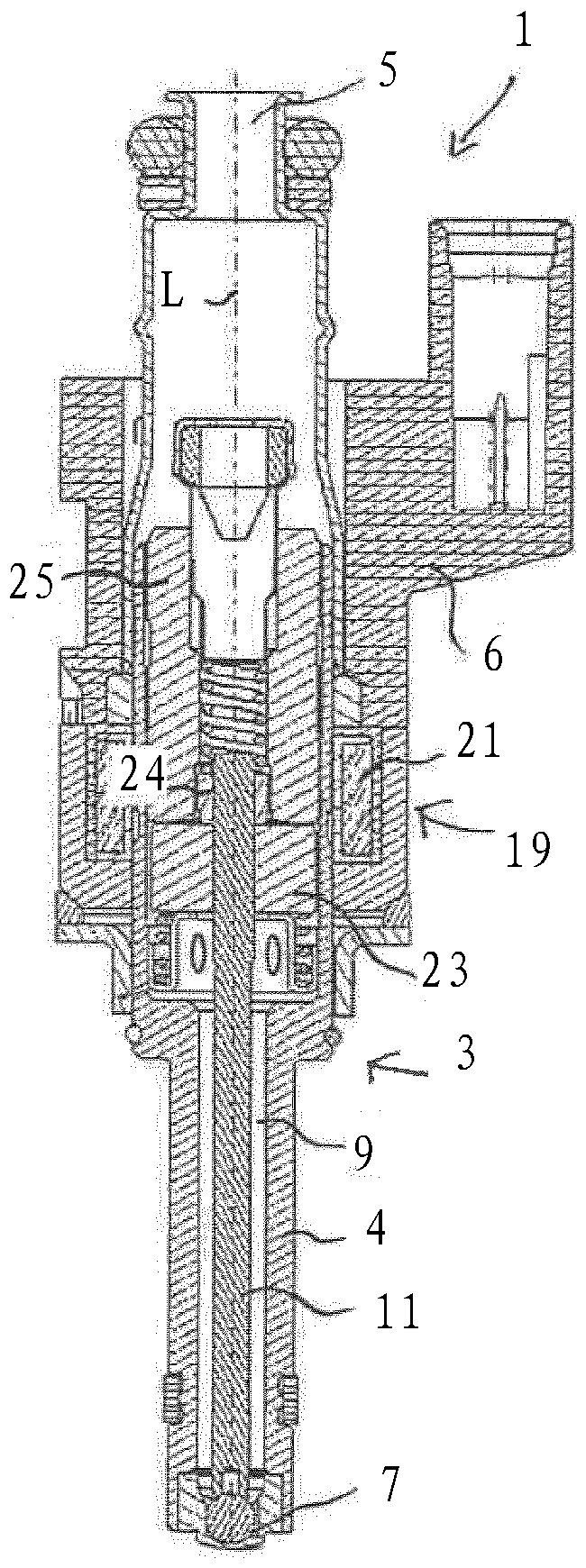
[0036] Such as figure 1 and 2 The fluid injection valve 1 shown in is particularly suitable for metering fuel to combustion engines. However, the invention can also be used for other types of injection valves.

[0037] Injection valve 1 includes a valve assembly 3 . The valve assembly 3 comprises a valve body 4 having a central longitudinal axis L. As shown in FIG. The housing 6 is arranged partially around the valve body 4 .

[0038]The valve body 4 includes a chamber 9 . The chamber 9 has a fluid outlet portion 7 . The fluid outlet portion 7 communicates with the fluid inlet portion 5 provided in the valve body 4 . The fluid inlet portion 5 and the fluid outlet portion 7 are in particular positioned at opposite axial ends of the valve body 4 . Chamber 9 receives valve needle 11 . The valve needle 11 includes a needle shaft and a sealing ball welded to the end of the needle shaft.

[0039] In the closed position of the valve needle 11 , the sealing ball rests sealing...


PUM


Abstract

Valve assembly for an injection valve and injection valve Valve assembly (3) for an injection valve (1), comprising a valve body (4) with a fluid outlet portion (7), a valve needle (11) preventing a fluid flow through the fluid outlet portion (7) in a closing position, a calibration spring (18) axially biasing the valve needle (11) in a closing direction towards the fluid outlet portion (5), an armature (23) of an electro-magnetic actuator unit (19), and an armature stopper (27). The armature stopper (27) comprises an armature support portion (31), a circumferential side wall (35) and a circumferential clamping portion (36). The circumferential clamping portion (36) has a circumferential gutter (37) formed by a base portion (39), an inner wall (40) being part of the circumferential side wall (35) and an outer wall (41) forming a press-fit area for press-fitting the armature stopper (27) into the valve body (4).

Description

technical field [0001] The present disclosure relates to valve assemblies for fluid injection valves and to fluid injection valves, such as fuel injection valves for vehicles. The present disclosure particularly relates to solenoid injection valves. Background technique [0002] Such injection valves must be able to meter fluid even at high fuel pressures. One design that ensures this is the "free lift" design, which is eg disclosed in document WO 2015 / 052281 A1. Depending on the design, the armature of the electromagnetic actuator unit travels approximately a "pre-travel gap" or "free lift gap" before it engages the needle to open the injector. Therefore, kinetic energy is accumulated before actually opening. [0003] Needle bounce events or post-injection are problematic for injection valves with "free lift" designs, as well as injection valves with other designs, because they result in increased emissions. Sometimes an anti-bounce armature spring is placed under the a...

Claims


Application Information

Patent Timeline
IPC IPC(8): F02M51/06
CPCF02M51/0671F02M51/0685F02M2200/304F02M2200/8061F02M2200/9015F02M2200/9053F02M51/0614
Inventor M.格兰迪S.菲利皮F.伦齐V.波利多里
Owner VTESCO TECH GMBH
Why Eureka
Try Eureka