
Device for testing constant thrust load of continuous linear motor

A linear motor, load testing technology, applied in measuring devices, force/torque/work measuring instruments, instruments, etc., can solve the problems of complex measurement process, single-pass measurement, poor accuracy, etc., and achieve simple device structure, low manufacturing cost, Reduce the effect of reducing errors

Inactive Publication Date: 2009-09-02
HARBIN INST OF TECH
View PDF0 Cites 14 Cited by
  • Summary
  • Abstract
  • Description
  • Claims
  • Application Information

AI Technical Summary

Problems solved by technology

[0003] The purpose of the present invention is to solve the problem that the test device for testing the constant thrust of a linear motor with loaded weights can only measure one way, the measurement process is complicated, and the accuracy is poor, and a continuous linear motor constant thrust load test device is provided

Method used


Image

  • Device for testing constant thrust load of continuous linear motor
  • Device for testing constant thrust load of continuous linear motor
  • Device for testing constant thrust load of continuous linear motor

Examples


specific Embodiment approach 1

[0010] Specific implementation mode one: the following combination image 3 Describe this embodiment, this embodiment comprises test platform 1, linear motor, magnetic powder brake 4, DC power supply 5, first synchronous wheel 6, second synchronous wheel 7 and synchronous belt 8, and linear motor comprises the mover 2 of linear motor and The stator 3 of the linear motor, the linear motor is arranged on the test platform 1, the linear motor is located between the first synchronous wheel 6 and the second synchronous wheel 7, one end of the test platform 1 is provided with a magnetic powder brake 4, the output shaft of the magnetic powder brake 4 is connected to the The first synchronous wheel 6 is fixedly connected, and the two ends of the synchronous belt 8 are respectively connected with the two ends of the mover 2 of the linear motor, and the mover 2 of the linear motor drives the first synchronous wheel 6 and the second synchronous wheel 7 to rotate through the synchronous be...

specific Embodiment approach 2

[0011] Embodiment 2: This embodiment differs from Embodiment 1 in that the diameters of the first synchronous wheel 6 and the second synchronous wheel 7 are equal, and other components and connection methods are the same as Embodiment 1.

specific Embodiment approach 3

[0012] Embodiment 3: The difference between this embodiment and Embodiment 1 is that the linear motor is a flat linear motor, a cylindrical linear motor or a double-sided linear motor, and other components and connection methods are the same as Embodiment 1.


PUM


Abstract

The invention relates to a device for testing the constant thrust load of a continuous linear motor, belonging to the field of motor test and aiming to solve the problems of one-way measurement, complicated measuring process and poor precision of a tester which adopts loaded weights to test the constant thrust of the linear motor. The device for testing the constant thrust load of the continuous linear motor comprises a test platform, the linear motor, a magnetic powder brake, a direct current supply, a first synchronizing wheel, a second synchronizing wheel and a synchronizing belt, wherein the linear motor comprises a linear motor mover and a linear motor rotor and is arranged on the test platform and between the first synchronizing wheel and the second synchronizing wheel; one end of the test platform is provided with the magnetic powder brake, and an output shaft of the magnetic powder brake is fixedly connected with the first synchronizing wheel; both ends of the synchronizing belt are respectively connected with both ends of the mover of the linear motor, the mover of the linear motor drives the first synchronizing wheel and the second synchronizing wheel to rotate by the synchronizing belt, and the direct current supply provides the magnetic powder brake with direct current. The tester is used for measuring the constant thrust of the linear motor.

Description

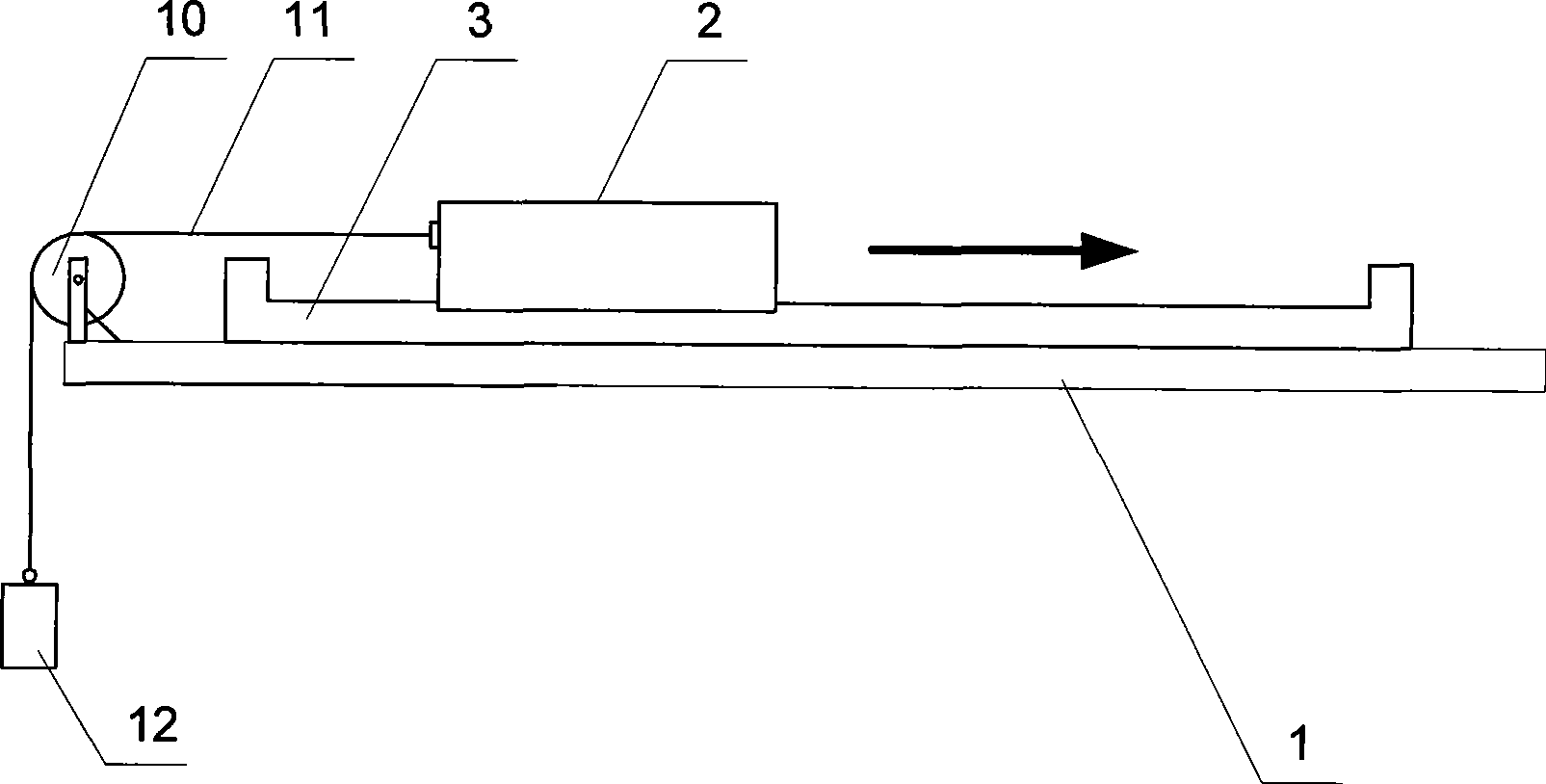
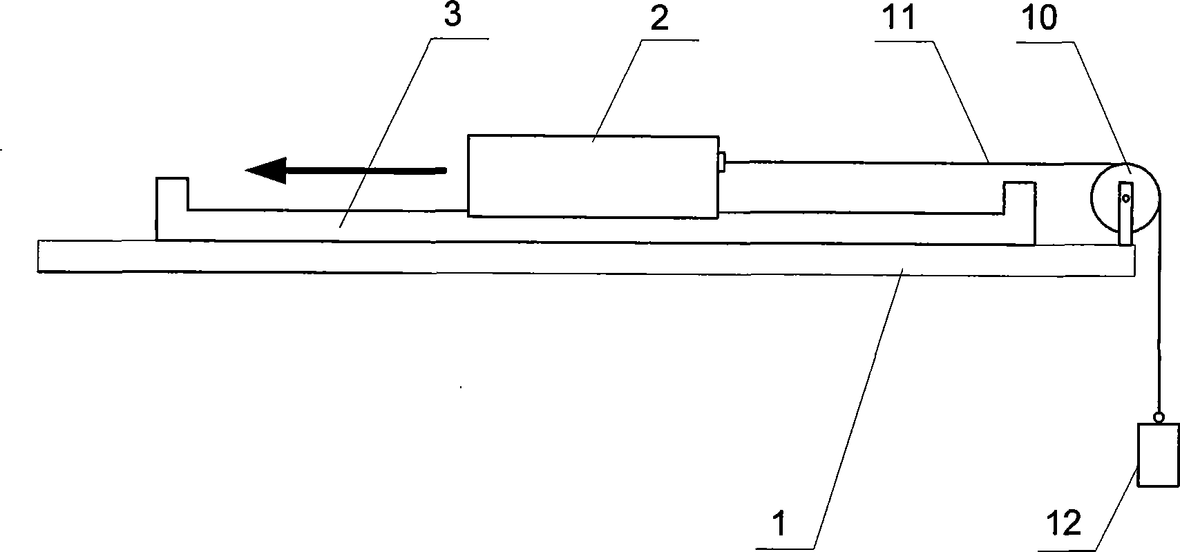
technical field [0001] The invention relates to a constant thrust load testing device for a continuous linear motor, which belongs to the field of motor testing. Background technique [0002] The existing linear motor constant thrust loading test device such as figure 1 and figure 2 as shown, figure 1 and figure 2 The schematic diagrams of the testing device for two directions of the linear motor are shown respectively. Through the pulley 10 and the transmission rope 11, the own weight of the weight 12 is added to the mover 2 of the linear motor to form a unidirectional pulling force to be loaded on the linear motor. Constantly changing the weight of the weight 12, when the linear motor reaches a constant speed, the braking thrust of the linear motor is equal to the weight of the weight 12, thus obtaining a constant thrust of the linear motor. The disadvantages of this test device are: (1) when testing the loading thrust, it can only measure in one direction and one w...

Claims


Application Information

Patent Timeline
Patent Type & Authority Applications(China)
IPC IPC(8): G01L5/12
Inventor 吴红星寇宝泉李立毅刘奉海洪作光
Owner HARBIN INST OF TECH
Learn More