
Marine power distribution and propulsion systems

A technology of propulsion system and distribution system, applied in ship propulsion, propulsion components, propulsion-based emission reduction, etc.

Inactive Publication Date: 2009-09-02
GE ENERGY POWER CONVERSION TECH
View PDF9 Cites 21 Cited by
  • Summary
  • Abstract
  • Description
  • Claims
  • Application Information

AI Technical Summary

Problems solved by technology

While these LVDC systems derive their DC current from MVAC current sources through current-limited power electronics, they rely on DC circuit breakers (DCCBs) to interrupt considerable fault currents

Method used


Image

  • Marine power distribution and propulsion systems
  • Marine power distribution and propulsion systems
  • Marine power distribution and propulsion systems

Examples


Embodiment Construction

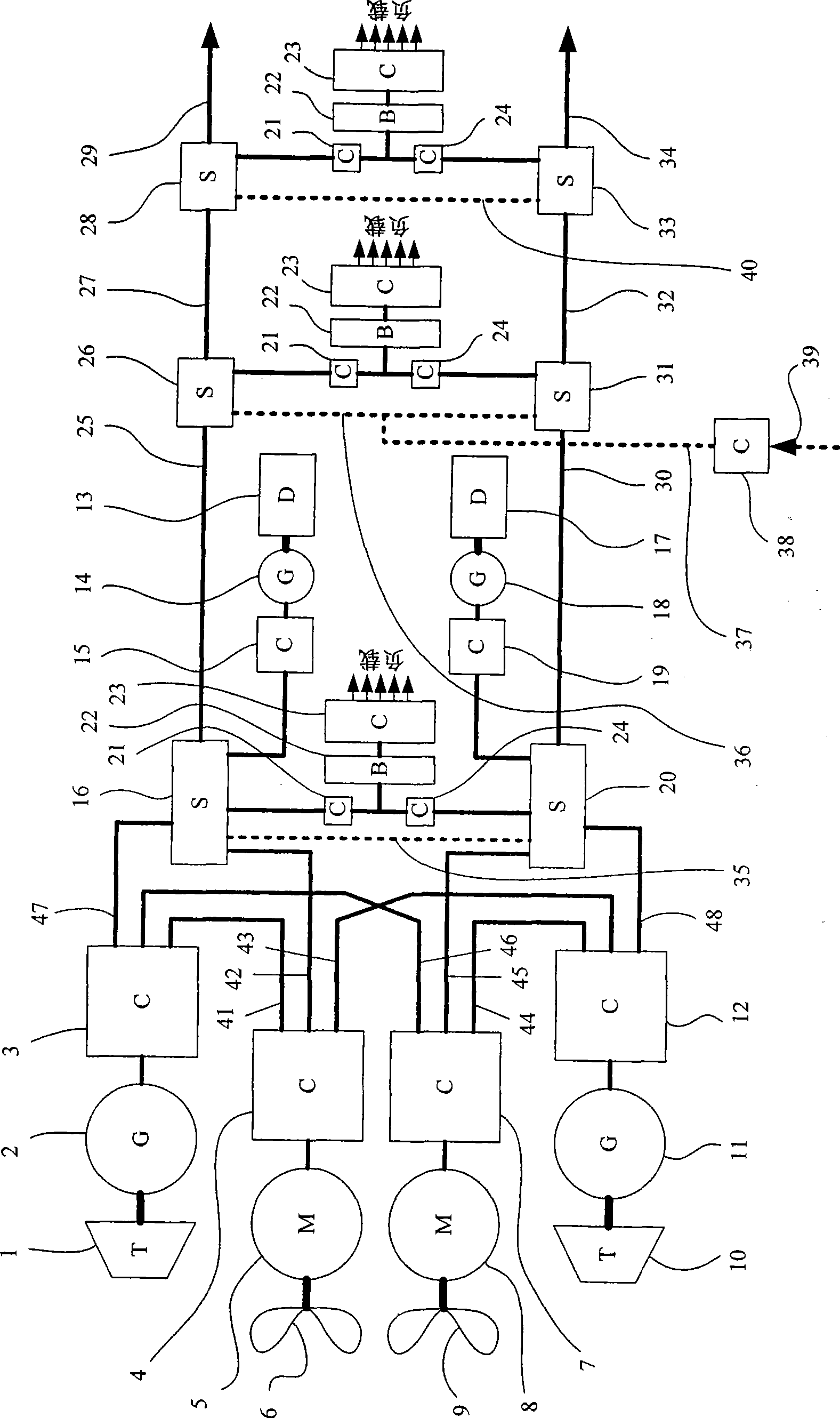
[0076] will now refer to figure 2 The basic layout of a ship's power distribution and propulsion system according to the invention is illustrated. It should be understood that figure 2 All inputs, outputs, terminations and interconnections are bipolar DC type.

[0077] A first propulsion power generation system (PPGS) comprises a turbine 1 driving a generator 2 to supply an output converter 3 . Similarly, the second PPGS comprises a turbine 10 driving a generator 11 to supply an output converter 12 . A first propulsion drive system (PDS) comprises a propeller 6 driven by a propulsion motor 5 , the power flow of which is regulated by a propulsion converter 4 . Similarly, the second PDS comprises a propeller 9 driven by a propulsion motor 8 whose power flow is regulated by a propulsion converter 7 . The output converters 3 and 12 each have three sets of outputs and the boost converters 4 and 7 each have three sets of inputs, all of which have a connection configuration whi...


PUM


Abstract

The present invention provides a power distribution system that can be used in naval ships and submarines. The power distribution and propulsion system includes a first propulsion drive system including a propulsion motor (5) having superconducting (preferably high temperature superconducting (HTS)) rotor windings and a power converter (4). A first propulsion power generation system supplies power to the first propulsion drive system and includes a generator (2) having superconducting (preferably HTS) rotor windings and a power converter (3). A first power generation system includes a power source (14) for supplying power to a first service distribution system that includes a dc distribution busbar (25) (optionally implemented using HTS cabling or busbar) for carrying a distribution voltage and a distribution current, and a switchboard 16 that includes protective switchgear with contacts. A power converter (15) is used to connect the power source (14) to the switchboard (16).

Description

technical field [0001] The present invention relates to a marine power distribution and propulsion system, and more specifically, to a system that achieves maximum power density, efficiency and stability, and facilitates the embedding of future technologies through a modular approach and standard interfaces. Background technique [0002] In traditional marine power distribution and propulsion systems employing full electric propulsion (FEP), fault current magnitude-time discrimination is used to enable protective switching devices to interrupt overcurrent faults in specific subcircuits, while enabling overcurrent faults in all other subcircuits. Actual damage is minimal. Such FEP systems are believed to utilize the "plant principle" in which the aim is to adapt the generating capacity fed into the grid at any given time to the total load being driven at that time. This has the effect of maximizing fuel efficiency. The configuration of such FEP systems is usually automated ...

Claims


Application Information

Patent Timeline
Patent Type & Authority Applications(China)
IPC IPC(8): B63H21/17H02J1/00H02J1/12
CPCB63G8/08B63H2021/173Y02T70/529B63H23/34B63G2007/065B63H21/17Y02T70/5263H02J1/102H02J1/14H02J1/16H02J4/00H02J7/34B60L3/04B60L2200/32B60L2220/42B60L50/10H02J2300/30H02J2310/42Y02T10/64Y02T10/7072Y02T70/50B60L1/00B63J3/04
Inventor 艾伦·戴维·克兰克莱夫·刘易斯
Owner GE ENERGY POWER CONVERSION TECH
Learn More