
Liuid crystal display device and its driving method

A technology of a liquid crystal display device and a driving method, which is applied to static indicators, nonlinear optics, instruments, etc., can solve the problems of unstable time, different effects, limited uses, etc., and achieve the effect of preventing image burn-in

Inactive Publication Date: 2009-08-19
SHARP KK
View PDF3 Cites 10 Cited by
  • Summary
  • Abstract
  • Description
  • Claims
  • Application Information

AI Technical Summary

Problems solved by technology

[0013] In the driving method described in Japanese Patent Laid-Open No. 59-119328 (Patent Document 1), although short-term burn-in can be prevented, long-term burn-in cannot be prevented.
In contrast to this, although the method for preventing burn-in of a liquid crystal monitor described in Japanese Patent Laid-Open No. 2004-325853 (Patent Document 2) aims at preventing burn-in caused by displaying the same image for a long time, Since the burn-in prevention operation is limited to when the image does not change, such as when neither the horizontal nor the vertical synchronization signal is input (power-saving standby mode), the timing of the screen burn-in prevention operation is not stable, and the effect is good. difference
In addition, when the backlight is turned off or when the display is completely black or completely white, no information is displayed, so the time for the burn-in prevention operation is actually in a standby state
As a result, the burn-in prevention method described in Japanese Patent Laid-Open No. 2004-325853 (Patent Document 2) has a problem of limited applications.

Method used


Image

  • Liuid crystal display device and its driving method
  • Liuid crystal display device and its driving method
  • Liuid crystal display device and its driving method

Examples


Embodiment approach

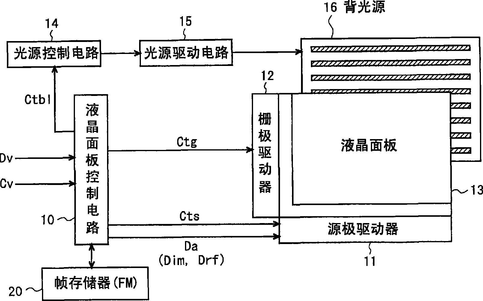
[0131] Next, refer to Figure 2 to Figure 12 One of the embodiments of the present invention will be described.

[0132]

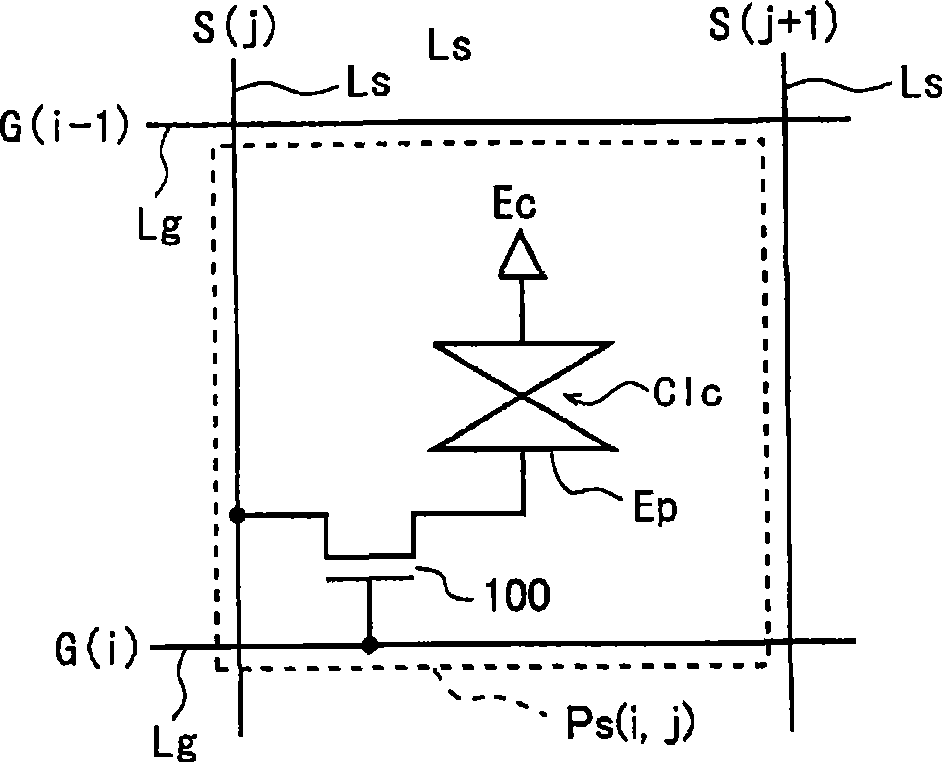
[0133] figure 2 It is a block diagram showing the configuration of a liquid crystal display device according to one embodiment of the present invention. This liquid crystal display device has an active matrix type liquid crystal panel 13, and in this liquid crystal panel 13, a plurality of (M) source lines as data signal lines extending in the column direction and a plurality of (M) source lines extending in the row direction are arranged in a grid form. A plurality of (N) gate lines as scanning signal lines are intersected, and a plurality of ( M×N) pixel forming part, that is, a pixel array. Each pixel forming part Ps(i, j) is as follows image 3As shown, a structure is adopted in which a thin film transistor (hereinafter referred to as a switching element) is provided with a source terminal connected to a data signal line Ls passing through a cor...


PUM


Abstract

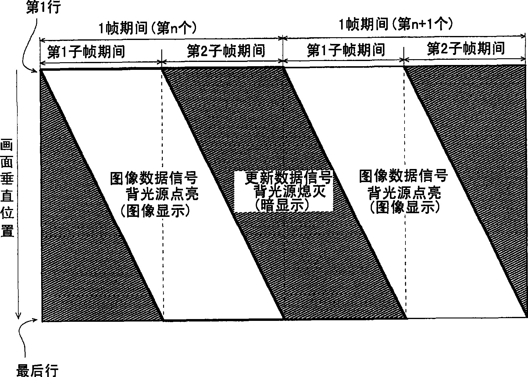
It is an object to provide a liquid crystal display device that always displays an image and at the same time that can prevent burning-in due to a long time display of the same image. In the liquid crystal display device provided with groups of pixel defining units disposed in a matrix-like structure and a back light controllable to turn on or off for each region corresponding to the prescribed number of scanning lines, each frame period of an input video signal is divided into first and second sub-frame periods, a liquid crystal panel is provided with a data signal based on the input video signal in response to the selection of the scanning lines for the first sub-frame period, and the liquid crystal panel is provided with a data signal based on refreshing data to prevent the burning-in of the image for the first sub-frame period. In each region, a unit of the back light turns on or off. When a data signal based on an input signal is supplied to the groups of the pixel defining units on the scanning lines corresponding to each region, the unit of the back light turns on. However, when a data signal based on the refreshing signal is supplied to each region, the unit of the back light turns off.

Description

technical field [0001] The present invention relates to a liquid crystal display device, and in more detail, relates to a technology used in the liquid crystal display device to prevent image burn-in caused when the same image is displayed for a long time. Background technique [0002] In a liquid crystal display device, a TFT (Thin Film Transistor: thin film transistor) type active matrix system is often used. Figure 16 It is an exploded perspective view showing a schematic structure of a liquid crystal panel of a general TFT liquid crystal display device, and shows a structure corresponding to four pixels. A liquid crystal panel generally adopts the following structure: an active matrix substrate (hereinafter referred to as "TFT substrate") 2 in which pixel circuits including TFTs as switching elements and pixel electrodes are arranged in a matrix; The opposing substrate 3 which is laminated with opposing electrodes and alignment films over the entire surface of the perma...

Claims


Application Information

Patent Timeline
Patent Type & Authority Applications(China)
IPC IPC(8): G09G3/36G02F1/133G09G3/20G09G3/34
CPCG09G2310/024G02F2001/133601G09G3/342G02F2001/133397G09G3/3648G09G2320/046G02F1/133397G02F1/133601
Inventor 山田直津幡俊英
Owner SHARP KK
Learn More