Flexible bus bar connector

A wire connector, metal technology, applied in the direction of connection, connecting device parts, electrical components, etc., can solve the problems such as the height of the electrical connector cannot be lowered, the strength is not enough, and the looseness, etc., to achieve smooth and stable electrical transmission. The effect of increasing rigidity and strength and prolonging service life

Inactive Publication Date: 2009-08-12
DACHANG ELECTRONICS TECH SUZHOU CO LTD +2
View PDF1 Cites 4 Cited by
  • Summary
  • Abstract
  • Description
  • Claims
  • Application Information

AI Technical Summary

Problems solved by technology

[0004] If the above-mentioned electrical connectors want to achieve the purpose of electrical transmission, the contact points of the flexible cable and the contacts on the circuit board need to be connected through the setting of the conductive terminals. However, the conductive terminals mostly have upper arms parallel to each other. And the form of the lower arm makes the conductive terminal form a higher height, so that the insulating body must also match its height, so that the insulating body has a higher height, so that the overall height of the electrical connector cannot be lowered; and the flexible cable is Use one end of the movable rotating cover to press against the surface of the flexible cable to clamp and position the flexible cable, but the positioning force of only relying on one end of the movable rotating cover is obviously insufficient, and the movable rotating cover is easily damaged by the influence of the conductive terminal. Jumping off, making the movable rotating cover loose and unable to effectively support the surface of the flexible cable, and the movable rotating cover is made of plastic material, which makes it not strong enough, so it cannot be firmly and effectively supported on the flexible cable surface

Method used


Image

  • Flexible bus bar connector
  • Flexible bus bar connector
  • Flexible bus bar connector

Examples


Embodiment Construction

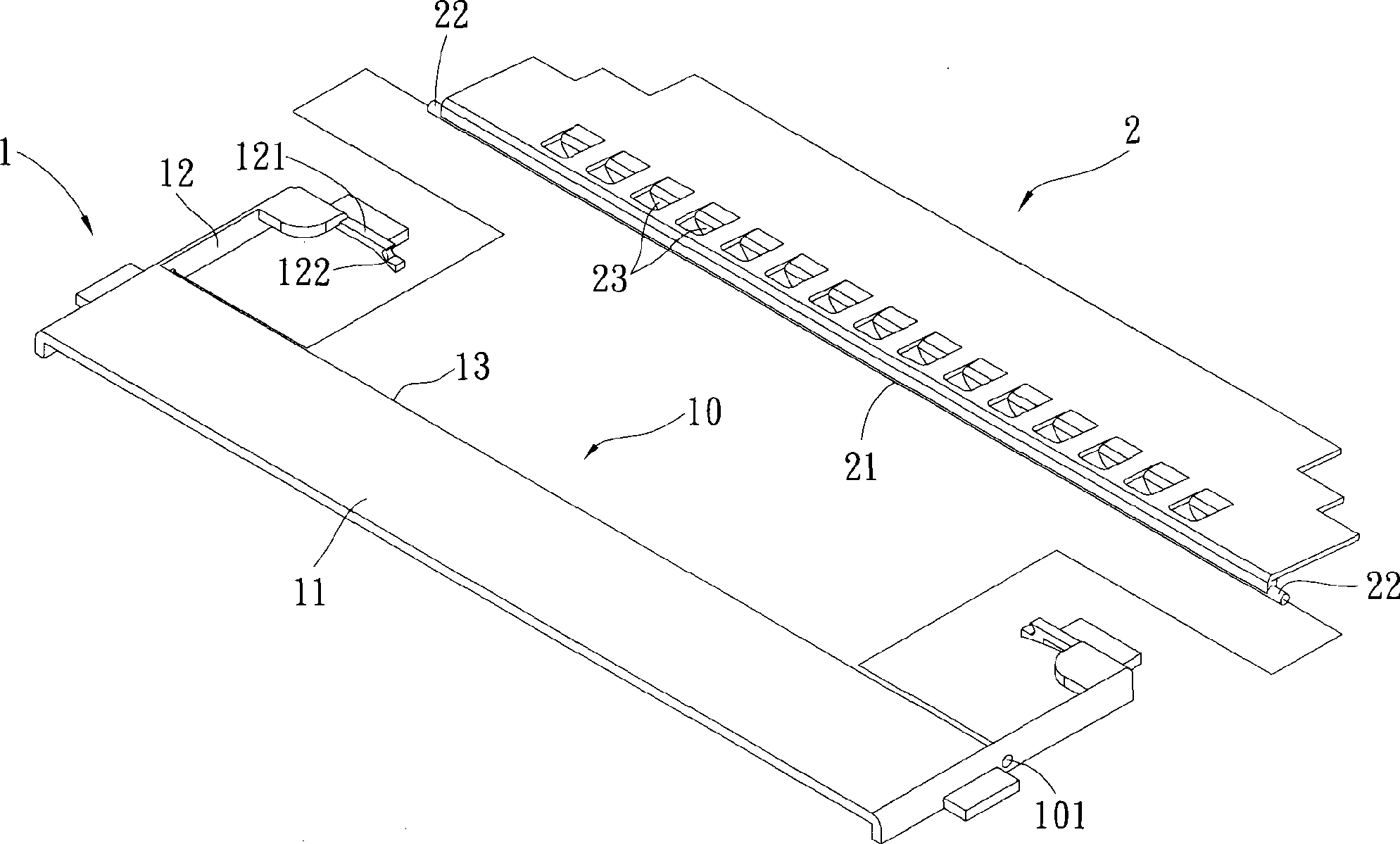
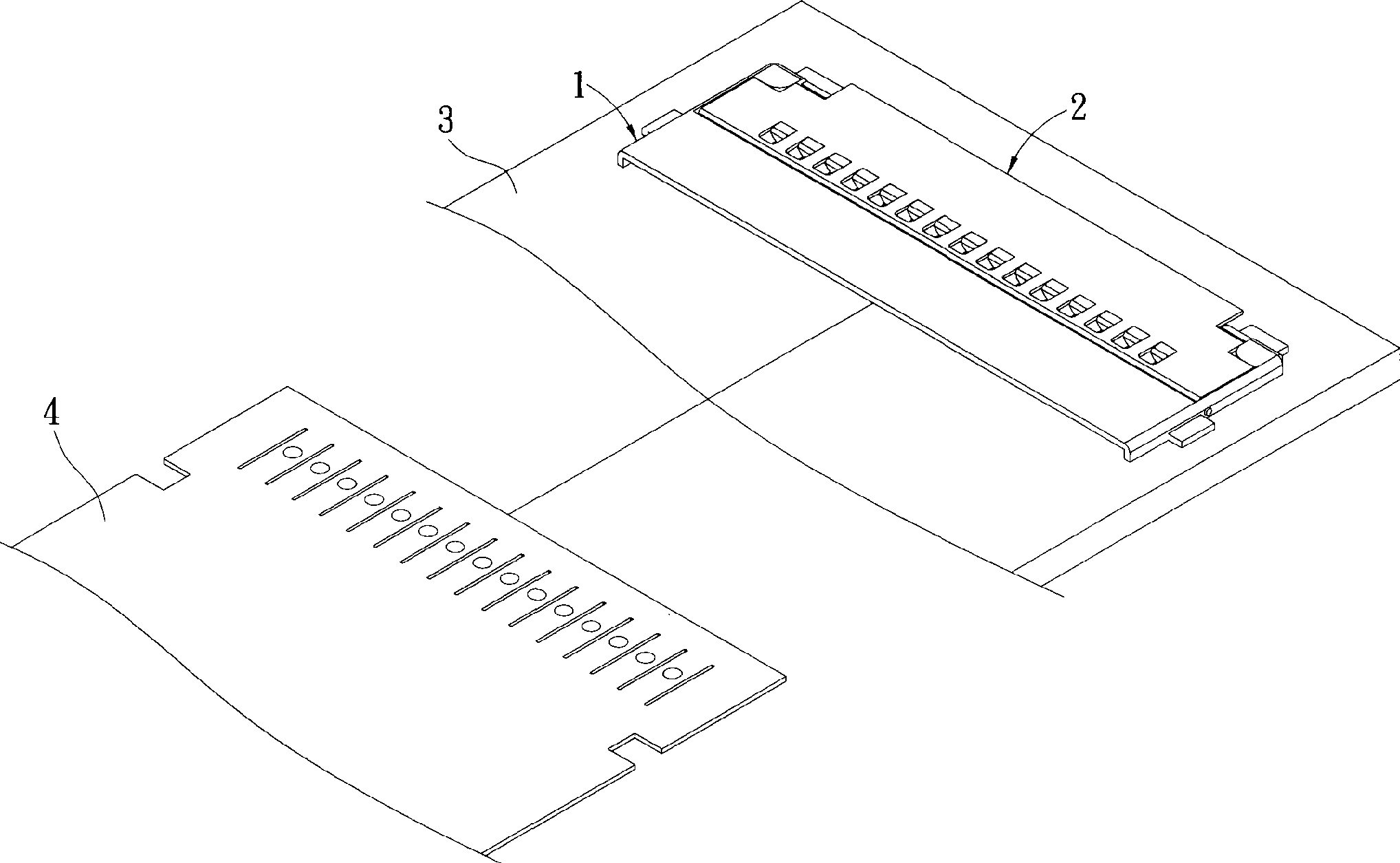
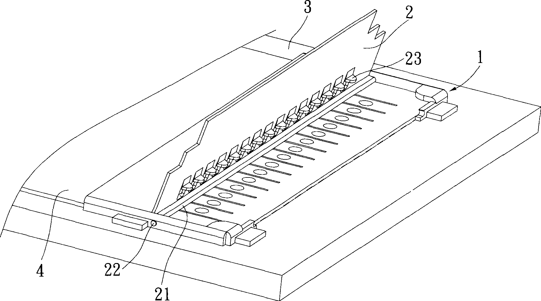
[0026] see Figure 1 to Figure 5 As shown, it is a diagram illustrating the specific implementation of the flexible cable connector of the present invention, please cooperate with the diagram for the following description. The flexible cable connector is composed of a thin base 1 and a metal flip cover 2; the thin base 1 can be used to be arranged on the top of the circuit board 3 for the insertion of the flexible cable 4, The structure and characteristics of each component will be described below firstly. In the embodiment of the present invention, the direction in which the flexible cable 4 is inserted is defined as the front:

[0027] The thin base 1 has a flat upper wall 11, and corresponding side walls 12 extending backward from both sides of the upper wall 11, so that the upper wall 11 and the two side walls 12 together form a receiving space 10, and the The rear end of the upper wall 11 is provided with an opening 13, and a corresponding shaft hole 14 is respectively p...


PUM


Abstract

The invention relates to a flexible ribbon cable connector, which is used for fixing a flexible ribbon cable. The flexible ribbon cable connector comprises a thin type base and a metal flip cover, wherein the thin type base can be fixed on a circuit substrate and is provided with an upper wall and two side walls so as to form an accommodating space, and the upper wall is provided with an opening; and the metal flip cover is rotationally arranged at the position of the opening of the thin type base and provided with a baffle wall which extends in the direction of the circuit substrate and a plurality of fixing points. After one end of the flexible ribbon cable is inserted in the accommodating space of the thin type base and downward presses the flip cover, the tail end of the baffle wall and the fixing points simultaneously press the flexible ribbon cable so as to form a double-fixing mechanism.

Description

technical field [0001] The present invention relates to a flexible cable connector, in particular to a flexible cable connector capable of double stably positioning the flexible cable. Background technique [0002] The common flexible flat cable (Flexible Flat Cable, FFC) is a product that wraps signal lines in a plastic insulating film. Its biggest feature is its flexibility, and it is light in weight and thin in thickness. According to the size and shape of the internal space of electronic products, the three-dimensional line configuration is suitable for all kinds of thin, light and small electronic products, such as notebook computers, optical drives, disk drives, printers or mobile phones. When in use, the flexible cable itself is not directly connected to the circuit board, but is electrically connected through a connector fixed on the circuit board, and such connectors are generally called flexible cable connectors . [0003] Known flexible cable connectors, such as...

Claims


Application Information

Patent Timeline
Patent Type & Authority Applications(China)
IPC IPC(8): H01R12/24H01R13/629H01R12/79
Inventor 王建淳林敬恒
Owner DACHANG ELECTRONICS TECH SUZHOU CO LTD
Why Eureka
Try Eureka