
Apparatus for eliminating clearance between screw mandrel and nut

A technology of nuts and screw rods, which is applied in the direction of transmission devices, belts/chains/gears, mechanical equipment, etc., can solve problems affecting machining accuracy and achieve the effect of improving machining accuracy and eliminating gaps

Inactive Publication Date: 2009-08-12
袁志成
View PDF0 Cites 6 Cited by
  • Summary
  • Abstract
  • Description
  • Claims
  • Application Information

AI Technical Summary

Problems solved by technology

Its weak point is: screw mandrel 101 and nut 103 are screwed together, after screw mandrel 101 is fixed on the main nut 102, because there is a clearance error between screw threads, the positioning of screw mandrel 101 also produces a gap. Clearance error, which affects the accuracy of machining

Method used


Image

  • Apparatus for eliminating clearance between screw mandrel and nut
  • Apparatus for eliminating clearance between screw mandrel and nut
  • Apparatus for eliminating clearance between screw mandrel and nut

Examples


Embodiment Construction

[0013] The following descriptions are only preferred embodiments of the present invention, and therefore do not limit the protection scope of the present invention.

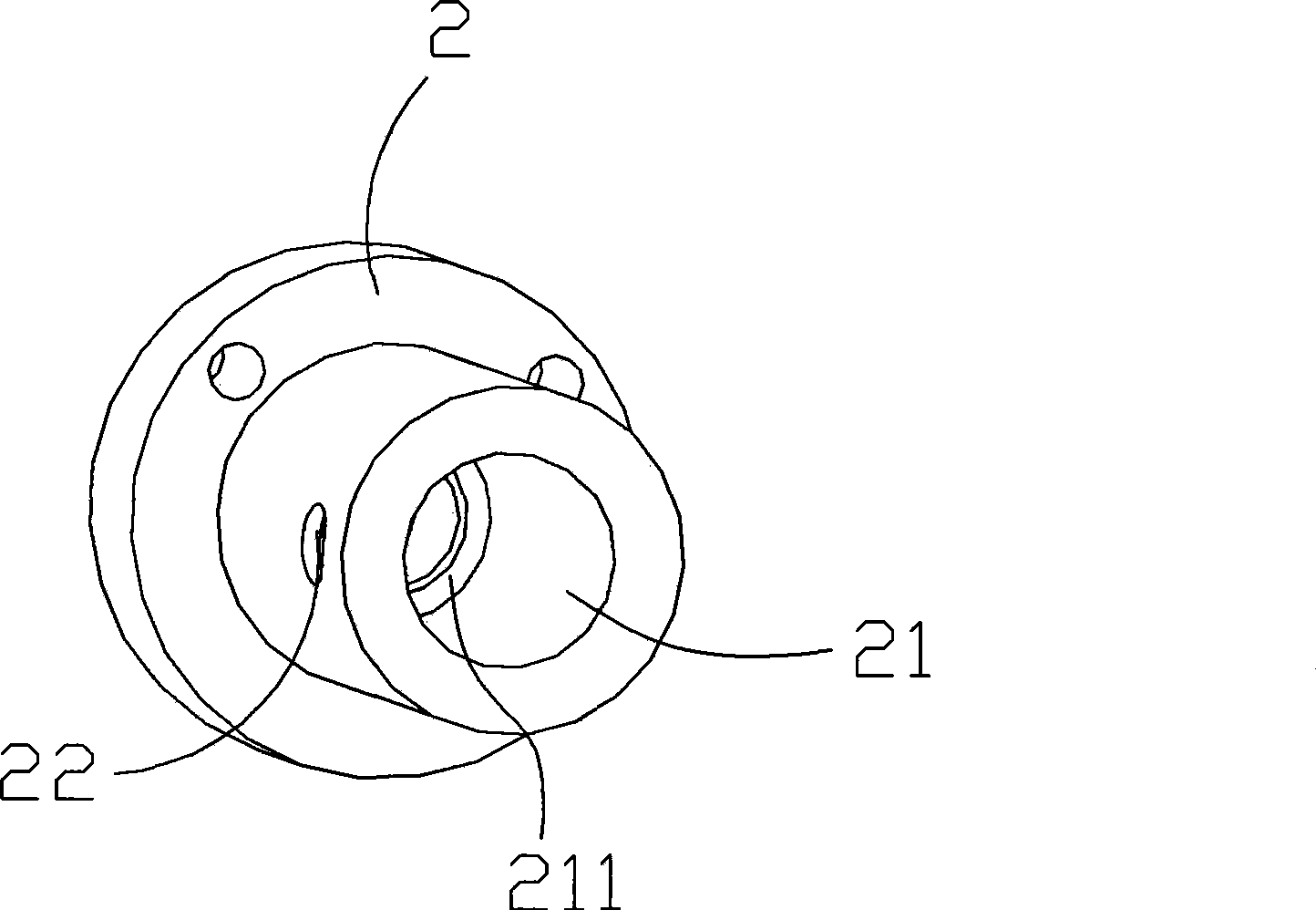
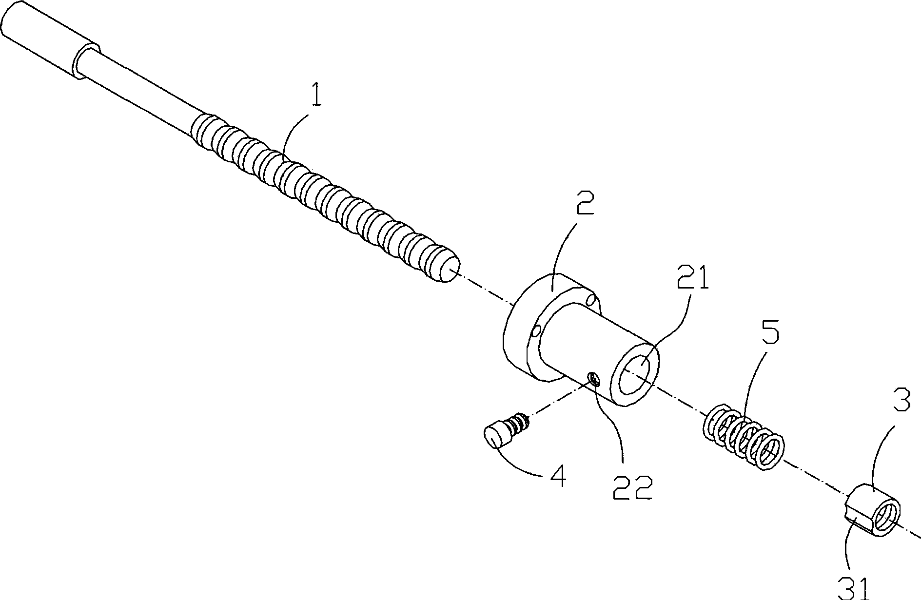
[0014] See figure 2 , 3 Shown: The gap elimination device between screw rod and nut, including screw rod 1, main nut 2, nut 3, and bolt 4, screw rod 1 is screwed in the receiving hole 21 in the main nut 2, screw rod 1 and nut 3 are screwed Together, the nut 3 is inserted into the receiving hole 22 of the main nut 2, the bolt 4 is screwed into the screw hole 22 on the main nut 2 and presses the nut 3; one end of the spring 5 acts on the nut 3, and the other end acts Force on the receiving hole 21 of the main nut 2 .

[0015] The receiving hole 21 of the main nut 2 has a step 211 , and one end of the spring 5 acts on the step 211 .

[0016] The nut 3 has a recessed surface 31 on which the bolt 4 is pressed.

[0017] Working principle: This device is equipped with a spring 5 in the main nut 2, and the elastic f...


PUM


Abstract

The invention relates to a device for eliminating a clearance between a screw rod and a nut, which comprises the screw rod, a main nut, the nut and a bolt. The screw rod is inserted into an accommodating hole of the main nut, the screw rod is screwed with the nut, the nut is screwed into the accommodating hole of the main nut, and the bolt is screwed into a screw hole on the main nut and presses the nut; and one end of a spring acts on the nut, and the other end of the spring acts on a step. The spring is additionally arranged on the main nut, and the elasticity of the spring acts on the nut, so the device radically eliminates the clearance between the screw rod and the nut, achieves zero error so as to greatly improve the mechanical processing precision.

Description

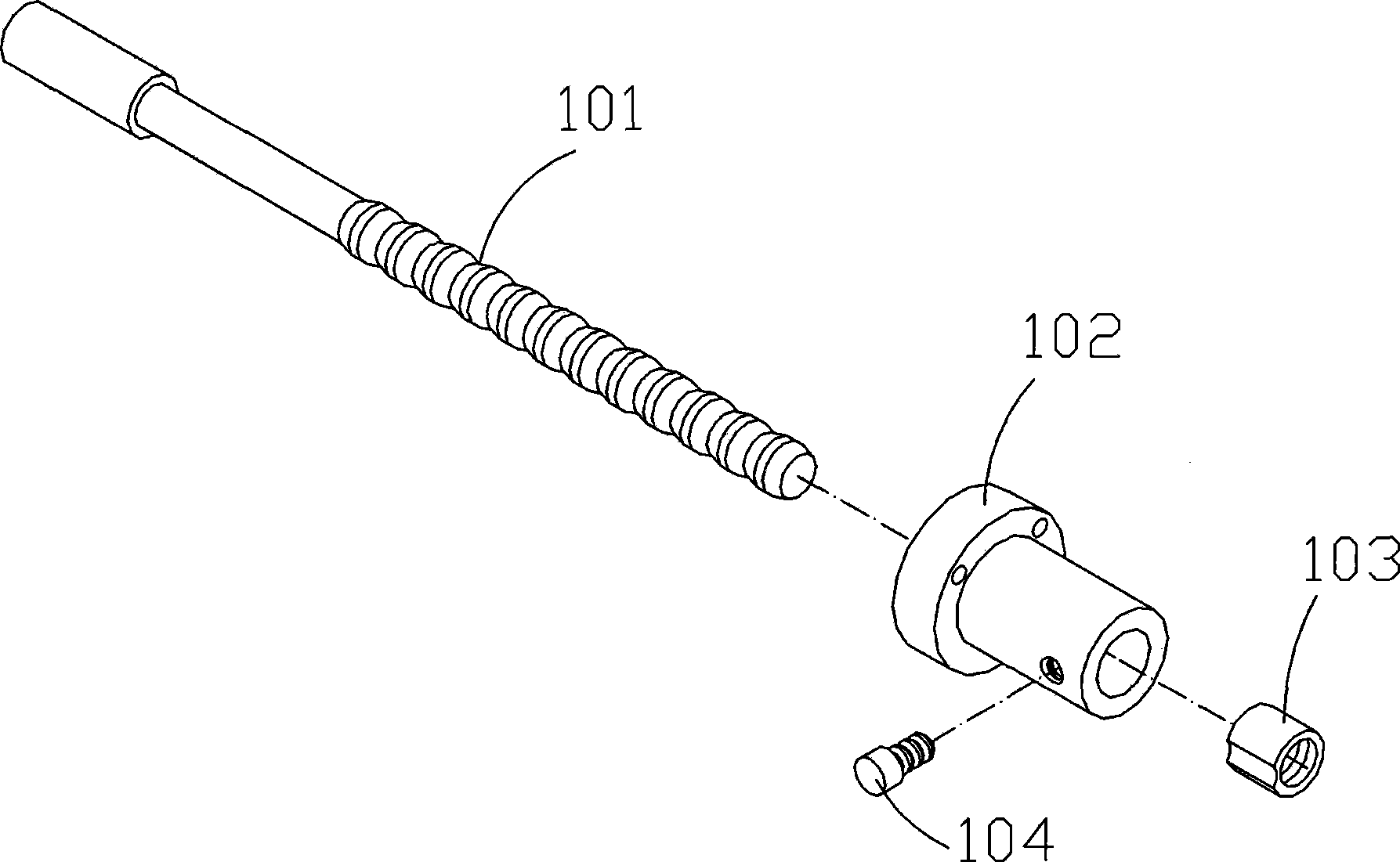
Technical field: [0001] The invention relates to the technical field of woodworking machinery, in particular to a screw and nut adjusting device in woodworking machinery. Background technique: [0002] Such as figure 1 As shown, the accuracy of the existing woodworking machinery is adjusted by the cooperation of the screw mandrel 101 and the nut 103. During use, the screw mandrel 101 is inserted into the main nut 102, the screw mandrel 101 and the nut 103 are screwed together, and the bolt 104 Through the hole on the main nut 102, it is fixed on the nut 103 and compressed, so as to control the distance between the screw mandrel 101 and the main nut 102, the positioning requires the length, width or high precision of the processed part. Its weak point is: screw mandrel 101 and nut 103 are screwed together, after screw mandrel 101 is fixed on the main nut 102, because there is a clearance error between screw threads, the positioning of screw mandrel 101 also produces a gap. ...

Claims


Application Information

Patent Timeline
Patent Type & Authority Applications(China)
IPC IPC(8): F16H25/20F16H25/22
Inventor 袁志成
Owner 袁志成
Learn More