Stabilized seal for rock bits

A technology of drill bit and sealing ring, used in construction and other directions, can solve problems such as sealing failure

Inactive Publication Date: 2009-08-05
BAKER HUGHES INC
View PDF0 Cites 5 Cited by
  • Summary
  • Abstract
  • Description
  • Claims
  • Application Information

AI Technical Summary

Problems solved by technology

This different contact pressure will cause the seal to fail

Method used


Image

  • Stabilized seal for rock bits
  • Stabilized seal for rock bits
  • Stabilized seal for rock bits

Examples


Embodiment Construction

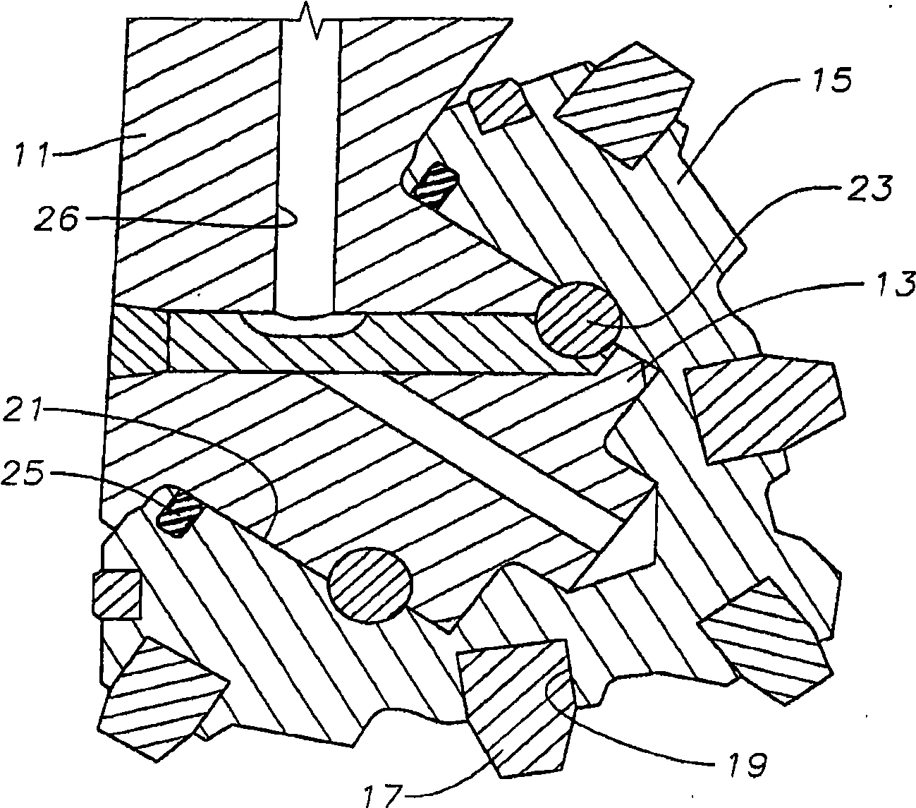
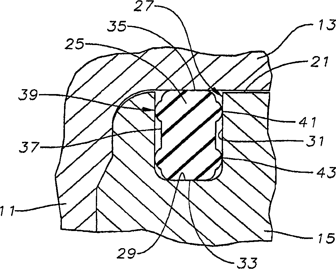
[0015] see figure 1 , the bit has a bit body 11 which typically has three suspended roller cone bit palms. A cylindrical cone shaft 13 is suspended from each cone bit leg of the bit body 11 . A cone 15 having a plurality of cutting elements 17 is rotatably mounted on the cone shaft 13 . In this example, the cutting element 17 comprises a tungsten carbide insert inserted in a mating hole 19 . Alternatively, the cutting elements 17 may comprise teeth turned into the outer surface of the cone 15 .

[0016] The cone 15 has a cavity with a cylindrical bearing surface 21 . The bearing surface 21 may be integrally formed with the cone 15, or may comprise a sleeve disposed within the cavity of the cone 15, such as by shrink fitting. The cone bearing surface 21 forms a radial bearing surface with the cone shaft 13 . Locking elements 23 , which in this example comprise a plurality of balls, are located in cooperating grooves on the cone shaft 13 and in the cavity of the cone 15 . ...


PUM


Abstract

An earth boring bit has a bit body having a depending bearing pin. A cone has a cavity rotatably mounted on the bearing pin. A seal groove formed in the cavity of the cone. An elastomeric seal ring is located within the groove and forms a seal between a base of the groove and the bearing pin. The seal ring has two side surfaces, each spaced from one of the side walls of the groove by a clearance. Elastomeric protuberances protrude from each of the side surfaces of the seal ring for non-sealing contact with one of the side walls of the groove.

Description

[0001] priority statement [0002] This application claims priority to US Provisional Application No. 60 / 837,560, filed August 14, 2006, and US Patent Application No. 11 / 838,361, filed August 14, 2007. technical field [0003] The present invention relates generally to rolling cone formation drill bits, and more particularly to a high aspect ratio elastomeric seal between a cone and a cone shaft having stabilized protrusions on at least one side surface. Background technique [0004] The rolling cone formation bit has a body with a threaded end that is connected to the drill string. The body typically has three suspended cone shafts, each rotatably mounted on a support cone. Each cone has cutting elements on its exterior for breaking up the formation as the bit body rotates. Each cone has a cavity that slides on one of the cone shafts. A lubricant reservoir supplies lubricant to the space between the cone cavity and the cone shaft. Typically, the lubricant system also ha...

Claims


Application Information

Patent Timeline
IPC IPC(8): E21B10/25
Inventor A·J·迪克
Owner BAKER HUGHES INC
Why Eureka
Try Eureka