Multi-gun type anti-explosion new energy vehicle intelligent charging device
A new energy vehicle and intelligent charging technology, applied in electric vehicle charging technology, charging stations, electric vehicles, etc., can solve problems such as endangering the personal safety of nearby personnel, short circuit of charging piles in contact with water, temperature explosion of charging piles, etc., and increase emergency repairs. time, reducing the chance of dumping, avoiding the effect of explosions
- Summary
- Abstract
- Description
- Claims
- Application Information
AI Technical Summary
Problems solved by technology
Method used
Image
Examples
Embodiment 1
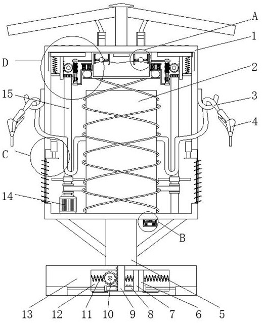
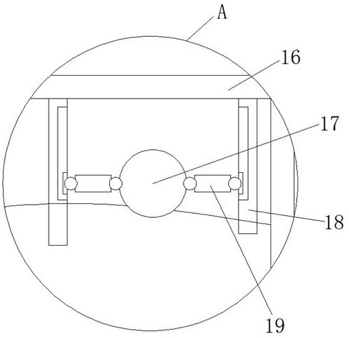
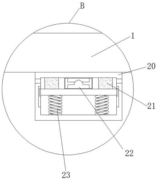
[0029] see Figure 1-7 , a multi-gun type explosion-proof new energy vehicle intelligent charging device, including a bottom plate 13, the inside of the bottom plate 13 is provided with a first chamber 12, the front inner wall of the first chamber 12 is slidably connected with a second rack 9, and the second rack 9 The top of the column 5 is welded with a column 5, the bottom right side of the column 5 is fixedly connected with a third box 20 by bolts, the bottom inner wall of the first box 1 is fixedly connected with a drive motor 14 by bolts, and the bottom inner wall of the first box 1 is set There is a charging pile 2, the top inner wall of the first box 1 is welded with a second box 16, the upward movement of the second rack 9 can make the column 5 move downward, so that the first box 1 moves upward, extending the first The time when the box body 1 is submerged increases the rush repair time of maintenance personnel.
Embodiment 2
[0031] see Figure 1-7, on the basis of Embodiment 1, the first chamber 12 is provided with a second electromagnet 7 and a first electromagnet 6, the first electromagnet 6 is located on the left side of the second electromagnet 7, the second electromagnet 7 and The first electromagnet 6 is welded with a first spring 11 on one side away from each other, and the other end of the first spring 11 is welded with the inner walls of both sides of the first chamber 12 respectively, and the back inner wall of the first chamber 12 is slidably connected with a first The tooth bar 8, the first tooth bar 8 moves to the left to make the first gear 10 rotate, and the right end of the first tooth bar 8 and the right bottom of the first electromagnet 6 are all welded with a connecting plate 38, and the connecting plates 38 are far away from each other. One side is welded with two support plates 37, the front inner wall of the first chamber 12 is rotatably connected with the first gear 10, the ...
Embodiment 3
[0033] see Figure 1-7 , on the basis of Embodiment 1, the top output end of the driving motor 14 is welded with the first rotating shaft 15, the driving motor 14 can be started to make the first pulley and the first rotating shaft 15 rotate, and the outer ring of the first rotating shaft 15 is welded with the first rotating shaft 15. Pulley, the right side of the bottom inner wall of the first box body 1 is connected with a second rotating shaft, the rotation of the second pulley can make the second rotating shaft rotate, the outer ring of the second rotating shaft is welded with a second pulley, and the rotation of the first pulley can be made by the belt. The second pulley rotates, the first pulley and the second pulley are connected by a belt, the top of the first rotating shaft 15 and the second rotating shaft are welded with a third gear 30, and the outer rings of the first rotating shaft 15 and the second rotating shaft are welded with fan blades The rotation of the fir...
PUM
 Abstract
Description
Claims
Application Information
 - Generate Ideas
- Intellectual Property
- Life Sciences
- Materials
- Tech Scout
- Unparalleled Data Quality
- Higher Quality Content
- 60% Fewer Hallucinations
Browse by: Latest US Patents, China's latest patents, Technical Efficacy Thesaurus, Application Domain, Technology Topic, Popular Technical Reports.
© 2025 PatSnap. All rights reserved.Legal|Privacy policy|Modern Slavery Act Transparency Statement|Sitemap|About US| Contact US: help@patsnap.com


