Servo system controlling method

A technology of a servo system and a control method, applied in the field of servo system control

Inactive Publication Date: 2010-12-22
BEIJING INSTITUTE OF TECHNOLOGYGY
View PDF1 Cites 0 Cited by
  • Summary
  • Abstract
  • Description
  • Claims
  • Application Information

AI Technical Summary

Problems solved by technology

However, since this method can only be applied to a specific system, when the controlled objects are different, it is necessary to change the reduction degree of the gear gap and the addition width of the dead zone

Method used


Image

  • Servo system controlling method
  • Servo system controlling method
  • Servo system controlling method

Examples


Embodiment Construction

[0034] Next, embodiments of the present invention will be described in detail with reference to the drawings.

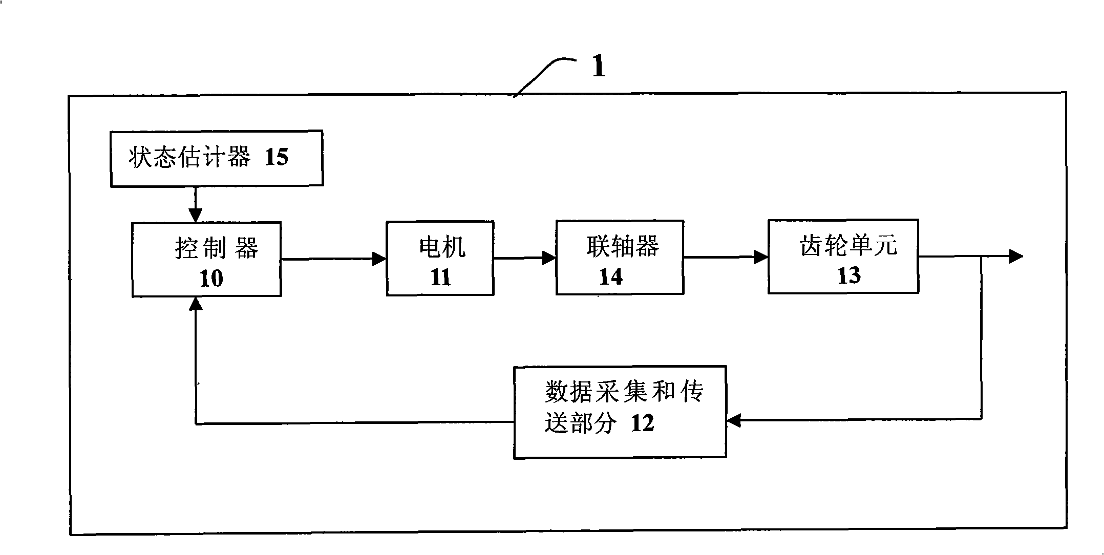
[0035] Such as figure 1 As shown, the servo system control device 1 includes a controller 10 , a motor 11 , a data acquisition and transmission part 12 , a gear unit 13 , a coupling 14 , and a state estimator 15 . The controller 10 completes the work of receiving data from the data acquisition and transmission part 12, calculating the control input quantity, outputting the control input quantity and so on. The motor 11 serves as a drive mechanism of the gear unit 13 . The data collection and transmission part 12 is used to collect the value of the current state variable, and transmit the collected value to the controller 10 . The coupling 14 is used to connect the motor 11 and the gear unit 13. When the controller 10 cannot receive the value of the current state variable from the data acquisition and transmission part 12, the controller uses the value of the curren...


PUM


Abstract

The invention provides a method for controlling a servo system, comprising the steps as follows: step 1: the clearance constraint condition of the servo system in a clearance mode is analyzed; step 2: the state equations of the system under two modes which are the clearance mode and the contact mode are integrated into the state equation of the system; step 3: the offline control law is stored ina storage module in a controller; step 4: the controller outputs a control input quantity u obtained by calculation to the motor, thus controlling the rotation speed of the motor; step 5: a data collecting and transmitting part collects the clearance angle of the gear unit and the rotation speed of the load-end motor and transmits the clearance angle and the rotation speed of the load-end motor to the controller; and the controller calculates the current control input quantity according to the collected clearance angle and the rotation speed of the load-end motor. In the method, the conditionthat the system is in the clearance mode is taken into account when the controller is designed, the offline control law is calculated in advance, and the offline controller is stored in the memory soas to facilitate the calculation of the current control input quantity during the real-time control process.

Description

technical field [0001] The invention relates to a servo system control method, in particular to a servo system control method with gap characteristics, which belongs to the technical field of servo system control. Background technique [0002] In the servo system, due to the use of high-speed motors, space constraints or the need to change the movement mode, transmission mechanisms such as gears, leadscrews, and worm gears are required. This type of transmission mechanism has gap characteristics from the structural point of view, and the impact of the gap on the transmission mechanism is more complicated. The static impact on the system will increase the static error of the system; the impact on the dynamic quality will cause the output phase to lag. Make the system unstable, strengthen the oscillation, and deteriorate the dynamic quality. [0003] In order to reduce the impact of the gap on the transmission mechanism and improve the stability of the servo system, the known...

Claims


Application Information

Patent Timeline
Patent Type & Authority Patents(China)
IPC IPC(8): G05B11/32G05B19/02
Inventor 陈杰窦丽华董领逊蔡涛彭志红白永强陈文颉潘峰张佳张娟
Owner BEIJING INSTITUTE OF TECHNOLOGYGY
Why Eureka
Try Eureka