Eureka AIR delivers breakthrough ideas for toughest innovation challenges, trusted by R&D personnel around the world.

Pyramid prism fixing device and method

A corner cube prism and fixing device technology, applied in installation, optics, instruments and other directions, can solve the problems of inability to fix, not easy to fasten the corner cube prism, etc., and achieve the effects of high installation accuracy, protection of the working plane, and simple structure

Inactive Publication Date: 2009-08-05
王利强 +1
View PDF0 Cites 17 Cited by
  • Summary
  • Abstract
  • Description
  • Claims
  • Application Information

AI Technical Summary

Problems solved by technology

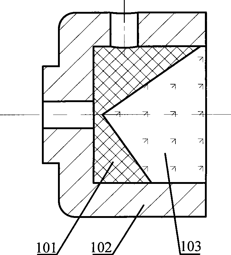
Because the contact distance between the bracket and the corner cube is short in the axial direction, and the installation accuracy depends on the matching accuracy of the short cylindrical part of the corner cube and the shallow groove of the mirror frame, it is not easy to fasten the corner cube, and at the same time, it can In order to ensure high installation accuracy, this corner cube prism bracket cannot be fixed figure 2 The tetrahedral corner cube shown

Method used


Image

  • Pyramid prism fixing device and method
  • Pyramid prism fixing device and method
  • Pyramid prism fixing device and method

Examples


no. 1 Embodiment

[0038] refer to Figure 5 , the fixing device of the corner cube prism includes a lock nut 501 , a rubber ring 502 , a clamp 504 , a base 505 and a set screw 506 . According to the positional relationship from the inside to the outside, the clamp 504 , the corner cube prism 503 , the rubber ring 502 and the locking nut 501 are located inside the base 505 in sequence.

[0039] refer to Figure 6 , there is a hollow hole 601 at the inner center of the fixture 504, the hole is hexagonal, and its cross section is a regular hexagon, the circumscribed circle diameter of the hollow hole is less than the diameter of the bottom surface of the corner cube prism 503; at the center of the bottom 603 of the fixture 504 A through hole 602 is opened. combine Figure 7 , the clamp 504 utilizes the end face vertex 701 of the hollow hole and the corner cube edge 702 to clamp together in a point contact manner, the through hole 602 is used to accommodate the tip of the corner cube, and the co...

no. 2 Embodiment

[0053] Such as Figure 9 As shown in (a), on the basis of the first embodiment, the hollow hole inside the fixture 504 is changed into a through hole that runs through the whole fixture, and a through hole is opened at the bottom of the base 505, and other parts are the same as the first embodiment. Two corner cubes can be fixed at the same time.

[0054] Such as Figure 9 As shown in (a), the corner cube fixing device includes a locking nut 901 , a rubber ring 902 , a clamp 904 , a base 905 and a set screw 906 . According to the positional relationship from the inside to the outside, the rubber ring 902 , the corner cube prism 903 , the fixture 904 , the corner cube prism 903 , the rubber ring 902 and the locking nut 901 are located inside the base 905 in sequence.

[0055] refer to Figure 9 (b), clamp 904 inner center is a through hole 907, and this through hole is hexagonal column shape, and its cross section is regular hexagon, and the circumscribed circle diameter of ...

no. 3 Embodiment

[0066] On the basis of the first embodiment, the hollow hole of the hexagonal prism of the fixture 504 is changed into the hollow hole of the hexagonal pyramid, and other parts are the same as the first embodiment, and this embodiment can be obtained. Contact-mounted corner cubes.

[0067] refer to Figure 10 , the corner cube fixing device includes a lock nut 1001 , a rubber ring 1002 , a clamp 1004 , a base 1005 and a screw 1006 . According to the positional relationship from the inside to the outside, the clamp 1004 , the corner cube prism 1003 , the rubber ring 1002 , and the locking nut 1001 are located inside the base 1005 in sequence.

[0068] refer to Figure 11 , there is a hollow hole 1101 at the inner center of the clamp 1004, which is a hexagonal pyramid hole and includes six ridgelines 1103, the ridgelines separated by two pairs are perpendicular to each other, the cross section of the hollow hole is a regular hexagon, and the hollow hole The diameter of the ci...


PUM


Abstract

The invention discloses a fixing device and a fixing method for a prism of corner cube. The fixing device comprises a clamp, an apron, a base, a lock nut and a holding screw. A hollow hole with a circum-circle diameter less than a bottom diameter of the prism of corner cube is arranged in the clamp and is used for placing the prism of corner cube. A hollow hole with an opening containing inner screw threads is arranged in the base and is used for placing the prism of corner cube and the clamp. The inner hole diameter of the lock nut is slightly less than the circum-circle diameter at the bottom of the prism of corner cube. The gap between the whole length of the hollow hole of the base and the length of the assembled prism of corner cube and clamp is less than the inner screw thread length of the base. The lock nut matches with the base through the inner and exterior screw threads and tightly locks the prism of corner cube in axial direction. The holding screw is screwed in the screw holes in the exterior wall of the base to tightly hold the clamp and prevent the clamp from rotating in the axial direction. The fixing device and a fixing method fully make use of the three orthogonal seamed edges of the prism of corner cube, adopts the three contact styles containing point contact, line contact and surface contact to realize the precisely-fixed prism of corner cube, and has the advantages of simple structure, convenient installation and detachable installation.

Description

technical field [0001] The invention relates to an installation and adjustment device of an optical element, in particular to a fixing device with a clamp for a corner cube prism. Background technique [0002] The corner cube prism, also known as the retroreflector, is an internal total reflection prism manufactured according to the principle of critical angle. It is not affected by the size of the incident angle, and reflects the incident light back in parallel to the original direction. Since the shape of the corner cube is not a regular cylinder or cuboid, and it is a glass product, it is brittle and easily broken, so it is difficult to install and fix it by mechanical means. [0003] The optical component product catalog published by EDMUND OPTICS of the United States in 2004 proposed a method and device for installing a corner cube (this product manual can also be retrieved through the following website: http: / / www.edmundoptics.com / onlinecatalog / displayproduct.cfm?pro...

Claims


Application Information

Patent Timeline
Patent Type & Authority Applications(China)
IPC IPC(8): G02B7/18
Inventor 王利强任文杰董绍忠何永利郑宏兴周毅铭杨明
Owner 王利强
Why Eureka
Eureka Blog
Learn More