
Method and apparatus for compensating for movement of a video

一种视频、运动的技术,应用在监视摄像机领域,能够解决视频图像模糊等问题,达到图像质量改善、图像模糊最小化的效果

Inactive Publication Date: 2009-07-29
PELCO INC
View PDF0 Cites 5 Cited by
  • Summary
  • Abstract
  • Description
  • Claims
  • Application Information

AI Technical Summary

Problems solved by technology

This degradation blurs the video image and results in a double image with ghosting-like appearance

Method used


Image

  • Method and apparatus for compensating for movement of a video
  • Method and apparatus for compensating for movement of a video
  • Method and apparatus for compensating for movement of a video

Examples


Embodiment Construction

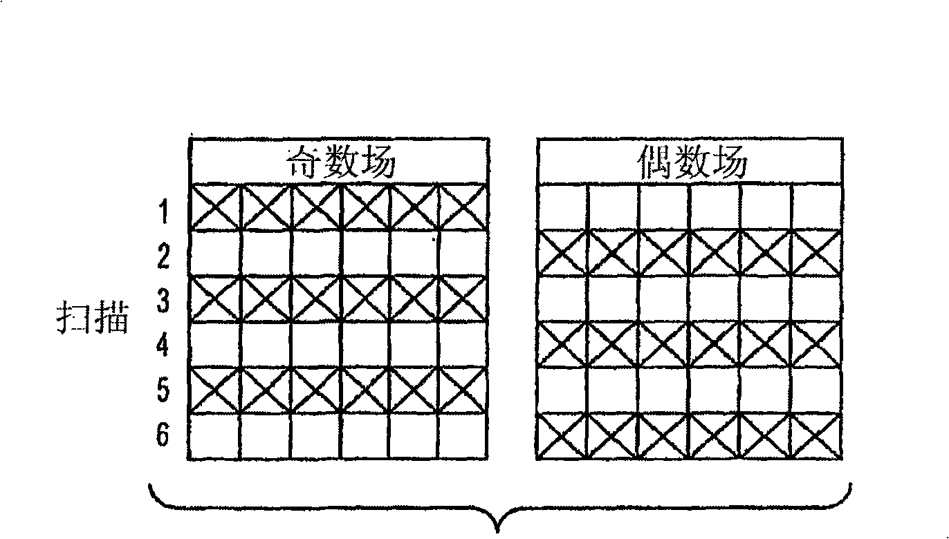
[0013] figure 1 A scan by an interlaced surveillance camera is shown. On the first scan by the surveillance camera, an odd field consisting of odd lines is captured, indicated by an X in the box for the first scan line under "Odd Field". In the second scan by the surveillance camera, an even field consisting of even lines is captured, which is indicated by an X in the box for the second scan line under "Even Field". The first and second scans include the first frame. Similarly, the third and fourth scans include the second frame, and the fifth and sixth scans include the third frame, as figure 1 shown in . For the NTSC system, each frame consists of 480 lines out of a total of 525 lines, with the remaining 45 lines used for sync, vertical retrace, and other data. However, it should be understood that other interlaced video file formats such as interlaced HDTV may also be used.

[0014] figure 2 An illustration of the perceived image when viewing a frame consisting of od...


PUM


Abstract

A method of compensating for the movement of a video surveillance camera comprising the steps of moving an interlaced camera, capturing a first video field of a frame at a first point in time, capturing a second video field of a frame at a second point jn time, determining the speed at which the camera is moving, and shifting the relationship between the first and second video fields based on the period of time between the first point in time and the second point fn time and the speed at which the camera is moving.

Description

Background of the invention [0001] The present invention relates to surveillance cameras, and more particularly to methods and apparatus for compensating image blur from motion video surveillance cameras. [0002] Video surveillance systems usually use an interlaced image display method to save video bandwidth and provide smooth pictures. In an interlaced display, the display alternates between drawing the even fields, which consist of the even lines of each frame, and the odd fields, which consist of the odd lines of each frame. As used herein, a frame consists of even and odd fields and refers to one of the still images that make up the motion video. Similarly, surveillance cameras used in these interlaced systems capture only half of the lines from each frame, ie one field at a time. Field pairs of each frame are perceived simultaneously, thereby appearing as complete frames due to the persistence of vision. [0003] Video surveillance cameras with motion often suffer fr...

Claims


Application Information

Patent Timeline
Patent Type & Authority Applications(China)
IPC IPC(8): H04N5/228
CPCH04N5/23248H04N5/23206H04N5/23264H04N5/23254H04N5/23261H04N23/661H04N23/68H04N23/6811H04N23/6815H04N23/682H04N23/63H04N23/695
Inventor S·N·格里戈里安Y·卡姆科R·塞克斯顿
Owner PELCO INC
Learn More