Teeth bar structure of optical disk driver

A technology of optical disc drives and racks, which is applied to instruments, recording/reproducing with optical methods, head configuration/installation, etc. It can solve the problems of difficult manufacturing, inaccurate precision, waste of manufacturing and assembly time, and parts costs

Inactive Publication Date: 2011-08-24
QUANTA STORAGE INC
View PDF0 Cites 0 Cited by
  • Summary
  • Abstract
  • Description
  • Claims
  • Application Information

AI Technical Summary

Problems solved by technology

[0004] However, the body 13 of this existing optical disc drive pickup head transmission mechanism 10 is not only complex in structure, difficult to manufacture, but also composed of multiple parts, which wastes manufacturing and assembly time and parts cost.
In addition, the two racks 16 of the pickup head transmission mechanism 10 of the existing optical disc drive are arranged on the outer end of the gear frame 15 together. The other rack 15 with the fixed end of the gear frame 15 and the elastic plate 17 as the bending fulcrum is also pushed out of the chute of the screw thread 18, resulting in slippage and jumping teeth, unable to transmit power to maintain the positioning accuracy of the main body 13 driving the reading head

Method used


Image

  • Teeth bar structure of optical disk driver
  • Teeth bar structure of optical disk driver
  • Teeth bar structure of optical disk driver

Examples


Embodiment Construction

[0079] The technical means adopted to realize the object of the present invention and their effects will be described below in conjunction with the accompanying drawings by taking preferred embodiments as examples.

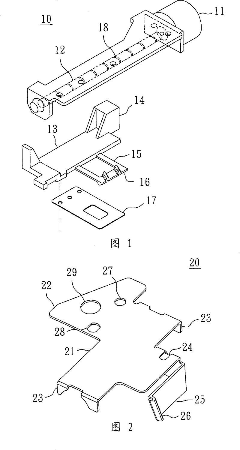
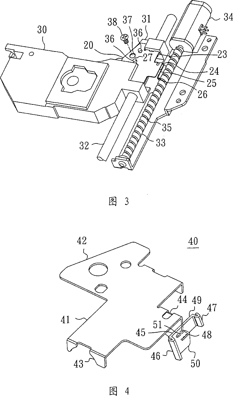
[0080] Please refer to figure 2 , which shows the rack structure 20 of the optical disc drive according to the first embodiment of the present invention. The rack structure 20 is integrally formed by stamping a metal plate, and includes a body 21 , a fixing portion 22 , a support frame 23 , a reinforcing body 24 , an elastic frame 25 and a rack 26 . The elastic frame 25 is mainly extended from the reinforcing body 24 at the front end of the main body 21, and the rack 26 is arranged on the elastic frame 25. The side of the main body 21 forms a support frame 23. Joint 31 (please refer to image 3 ) to form a link.

[0081] Wherein, the body 21 is in the shape of a flat plate for fixing to the joint portion 31 of the read head 30 , and its shape can be changed ac...


PUM


Abstract

The invention discloses the rack structure of an optical-disk drive, which is formed by the punching of a metal plate at one time. A main body is provided with a linking fixing part; the periphery of the main body is punched downwards and bended so as to form a support bracket; a part of the main body, which is close to the front end, is punched into a convex or concave slot so as to form a secondary reinforced body; a part at the front end, which is close to the middle part, is bended downwards so as to form a reinforced body; a flexible support extends from the front end of the reinforced body and is bended to be parallel with the front end of the main body and keeps an interval; the middle part of the flexible support is punched into a level crevice and forms an upper support and a lower support; an end connecting the upper support and the lower support is provided with a first rack; the other end of the lower support is linked with the reinforced body and extends so as to form a bending pivot point; the other end of the upper support forms a second rack used for enhancing the meshing with a screw stem.

Description

technical field [0001] The invention relates to an optical disc drive, in particular to a rack structure engaged with a drive screw rod in a transmission mechanism used by the optical disc drive to drive a pickup head to move back and forth. Background technique [0002] The function of the transmission mechanism of the optical disc drive is to move the read head to the correct position, so that the beam projected by the read head can be accurately aligned with the tiny data marks on the optical disc, so as to ensure the correctness of the read and write signals. While improving the precision of the transmission mechanism, focusing on miniaturization and reducing manufacturing costs are also the main research and development directions for the industry to improve the competitiveness of optical disc drive products. [0003] Such as figure 1 As shown, the figure shows the transmission mechanism 10 of the read head of the existing optical disk drive. The transmission mechanis...

Claims


Application Information

Patent Timeline
Patent Type & Authority Patents(China)
IPC IPC(8): G11B7/08G11B7/085
Inventor 邱曜嘉吴仁琛
Owner QUANTA STORAGE INC
Why Eureka
Try Eureka