Apparatus and method for storing storage units

A technology of storage unit and storage location, which is applied in the direction of storage devices, transportation and packaging, conveyor objects, etc., can solve the problems of inability to realize transfer redundancy, mutual obstruction of storage channels, etc., and achieve improved transit time and large transfer redundancy The effect of high speed and high transfer rate

Inactive Publication Date: 2009-07-22
SIEMENS AG
View PDF0 Cites 6 Cited by
  • Summary
  • Abstract
  • Description
  • Claims
  • Application Information

AI Technical Summary

Problems solved by technology

Such a transfer redundancy cannot be achieved even by using several vehicles, since the vehicles block each other in the storage lanes and thus only have very limited access to the storage units to be deposited and / or retrieved

Method used


Image

  • Apparatus and method for storing storage units
  • Apparatus and method for storing storage units
  • Apparatus and method for storing storage units

Examples


Embodiment Construction

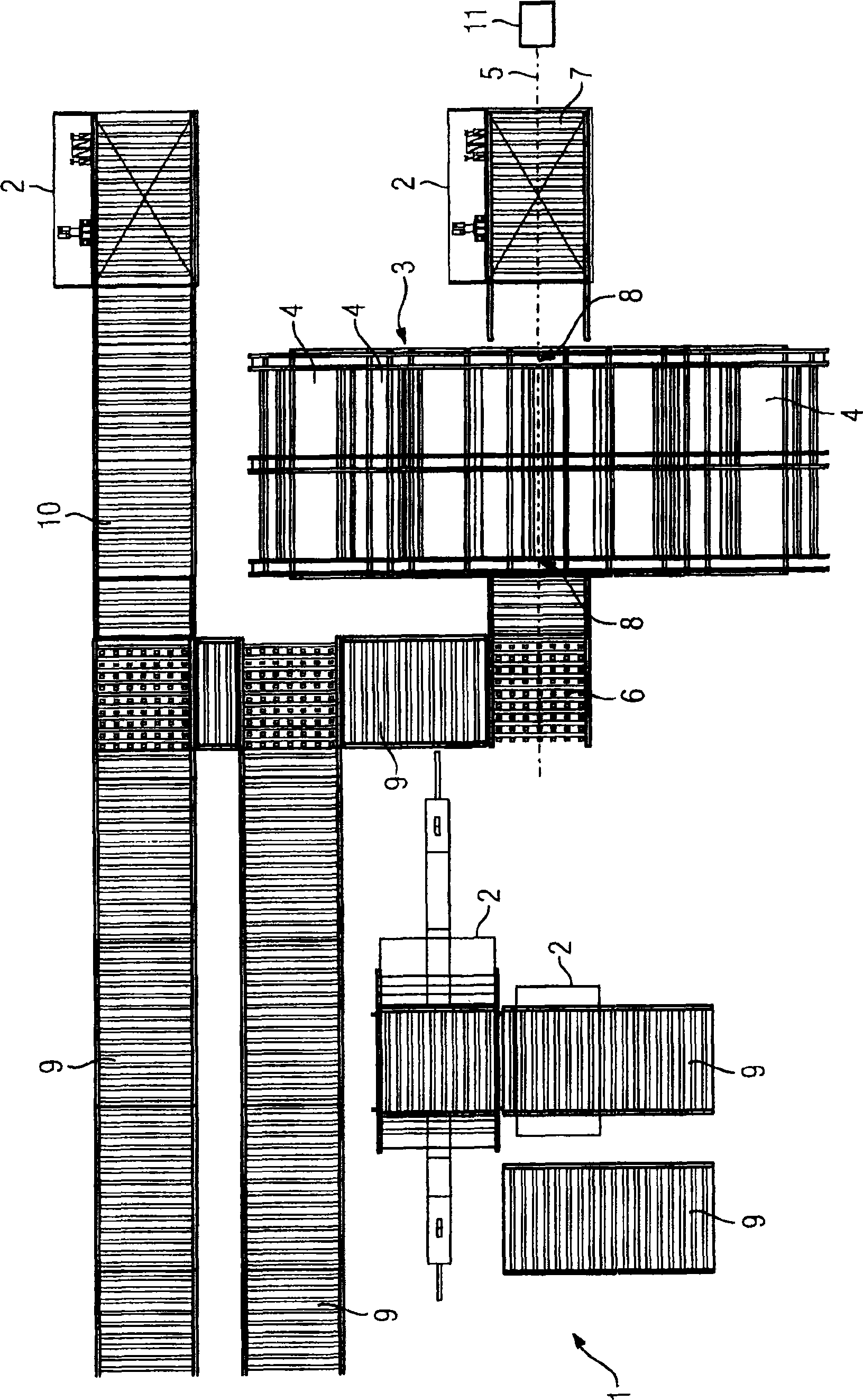
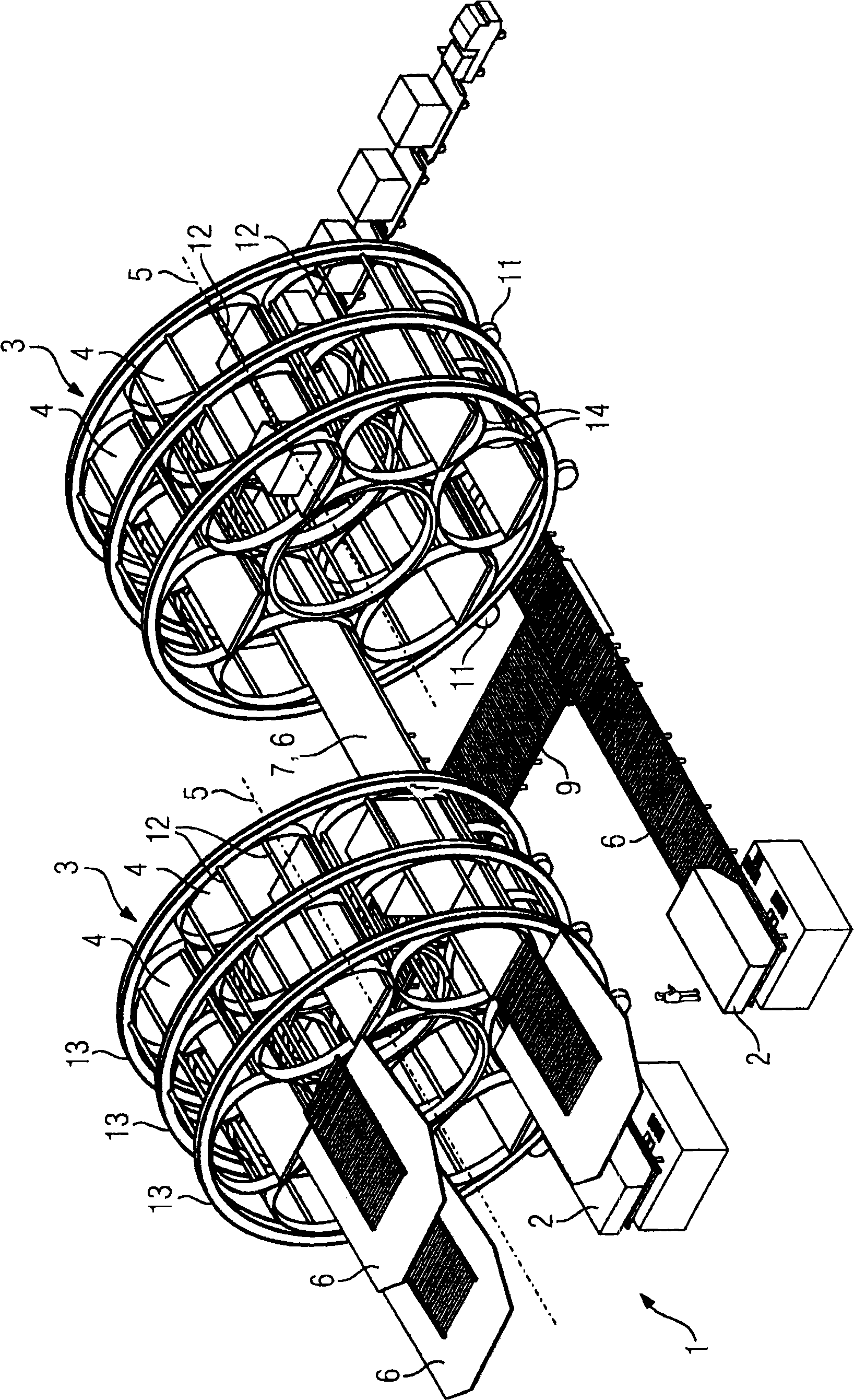
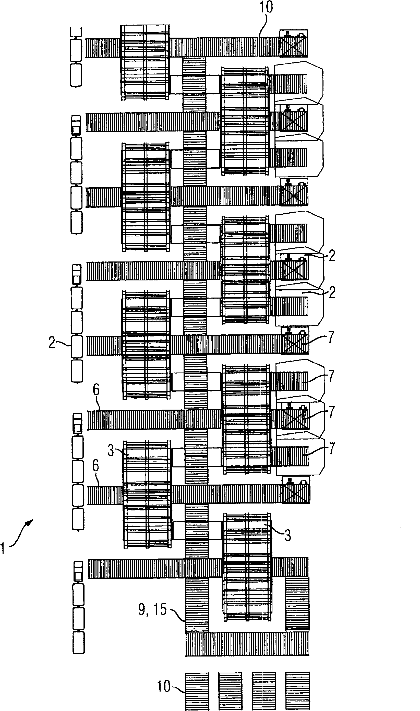
[0021] figure 1 A device 1 for storing storage units 2 (hereinafter simply referred to as device 1 ) is schematically shown. The device 1 is a transshipment location for storage units 2 which enables a high throughput for the storage units 2 by storing the storage units 2 according to the invention in a circular warehouse 3 with a plurality of storage locations 4 rate while having high storage capacity. In particular, piece containers, pallets or other suitable storage containers are used as storage units 2 . The storage location 4 is configured as a cavity for receiving at least one storage unit 2 . As an alternative, the storage location 4 can also be configured for receiving two or more storage units 2 for transfer redundancy. In this case, several storage units 2 can be loaded and / or called out simultaneously. This improves, in particular increases, the transit time of the device 1 .

[0022] The circular storehouse 3 is mounted rotatably about an axis of rotation 5 ....


PUM


Abstract

The invention relates to an apparatus (1) for storing storage units (2), in particular piece-goods containers, comprising at least one circular bearing (3) which can rotate about a rotational axis (5) and has a plurality of storage places (4) which are arranged in a circular manner around the rotational axis (5).

Description

technical field [0001] The invention relates to a device and a method for storing storage units, in particular unit load containers, so-called ULDs (=unit-load-device). Background technique [0002] Usually in ports or freight train stations or in transshipment workshops, e.g. with floor warehouses for block-storage of similar goods (blockstapelung) or with high-bay warehouses for transshipment storage units such as piece containers or pallets, such as container transshipment facilities , using ground conveying equipment or ground conveying vehicles, such as lifting transfer vehicles (also referred to as ELT, where ELT=elevating transfer vehicle), forklifts, straddle vehicles, rail vehicles and / or mobile crane equipment such as gantry cranes, bridge cranes and / or mobile container trucks. The storage unit is transported or transported by means of a vehicle or a ground transport vehicle for depositing or recalling a storage location or for moving the storage unit back and for...

Claims


Application Information

Patent Timeline
Patent Type & Authority Applications(China)
IPC IPC(8): B65G1/127B65G47/51
Inventor M·克莱因
Owner SIEMENS AG
Why Eureka
Try Eureka