
Lifting mechanism

A lifting mechanism and roller technology, which is applied in the direction of supporting machines, mechanical equipment, machine tables/supports, etc., can solve the problems of sudden drop of the LCD screen, heavy weight of the lifting mechanism, poor stability of the lifting mechanism, etc., and achieve compact structure and manufacturing process The effect of mature and stable positioning

Inactive Publication Date: 2009-07-22
HONG FU JIN PRECISION IND (SHENZHEN) CO LTD +1
View PDF0 Cites 14 Cited by
  • Summary
  • Abstract
  • Description
  • Claims
  • Application Information

AI Technical Summary

Problems solved by technology

[0005] However, this liquid crystal display lifting mechanism adopts the lifting block 6 to cooperate with the lifting seat 5. Although the lifting adjustment function can be realized, in order to ensure that the lifting block 6 has sufficient strength to support the liquid crystal display screen, the lifting block 6 usually has a larger weight. and volume, and the lifting seat 5 matched with the lifting block 6 also has a relatively large weight and volume, resulting in a large weight and high manufacturing cost of the entire lifting mechanism.
In addition, the lifting mechanism realizes the positioning at the desired position through the friction force between the lifting block 6 and the lifting seat 5, but the friction force is limited, and the impact of external force is likely to cause the liquid crystal display to drop suddenly. Therefore, the stability of the lifting mechanism poor

Method used


Image

  • Lifting mechanism
  • Lifting mechanism
  • Lifting mechanism

Examples


Embodiment Construction

[0013] A preferred embodiment of the present invention is a lifting mechanism, which is suitable for electronic devices with display screens. In this embodiment, the elevating mechanism applied in the liquid crystal display supporting device is taken as an example for illustration.

[0014] see figure 2 , the liquid crystal display support device 10 includes a lifting mechanism 20, a display support frame 30 and a base 40, wherein the lifting mechanism 20 is connected to the display support frame 30 and the base 40 respectively.

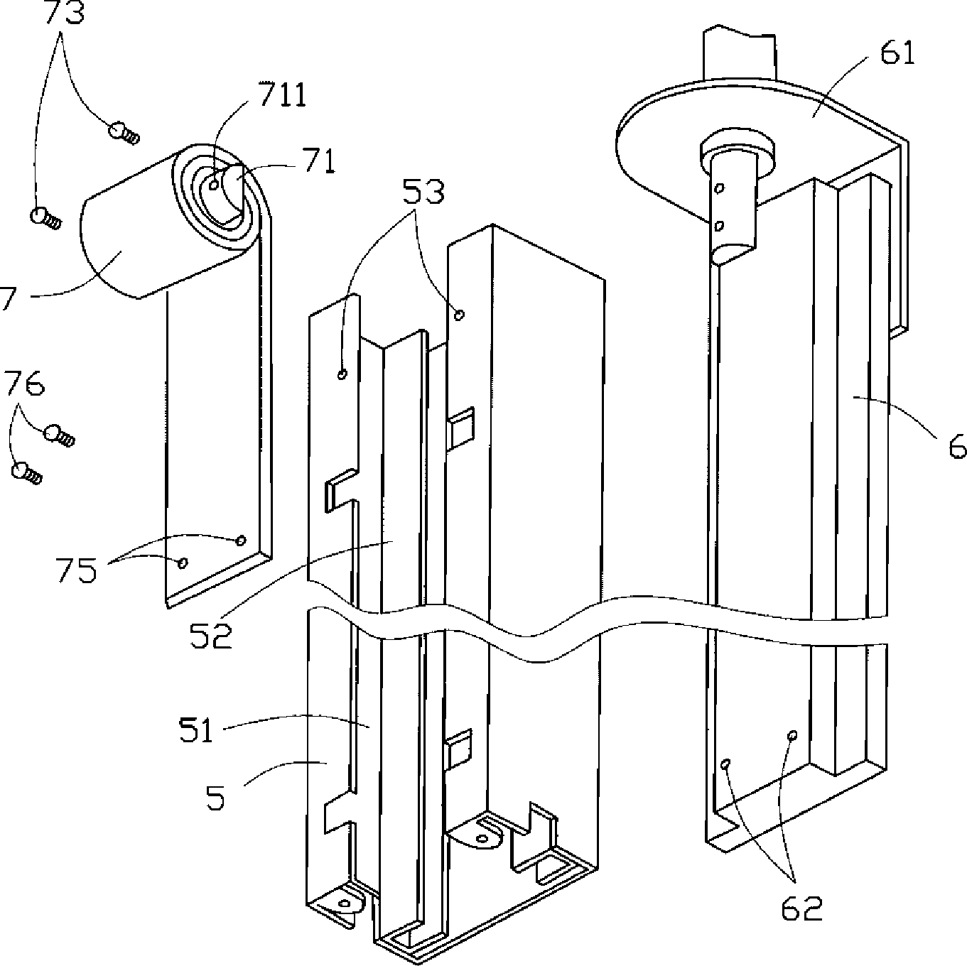
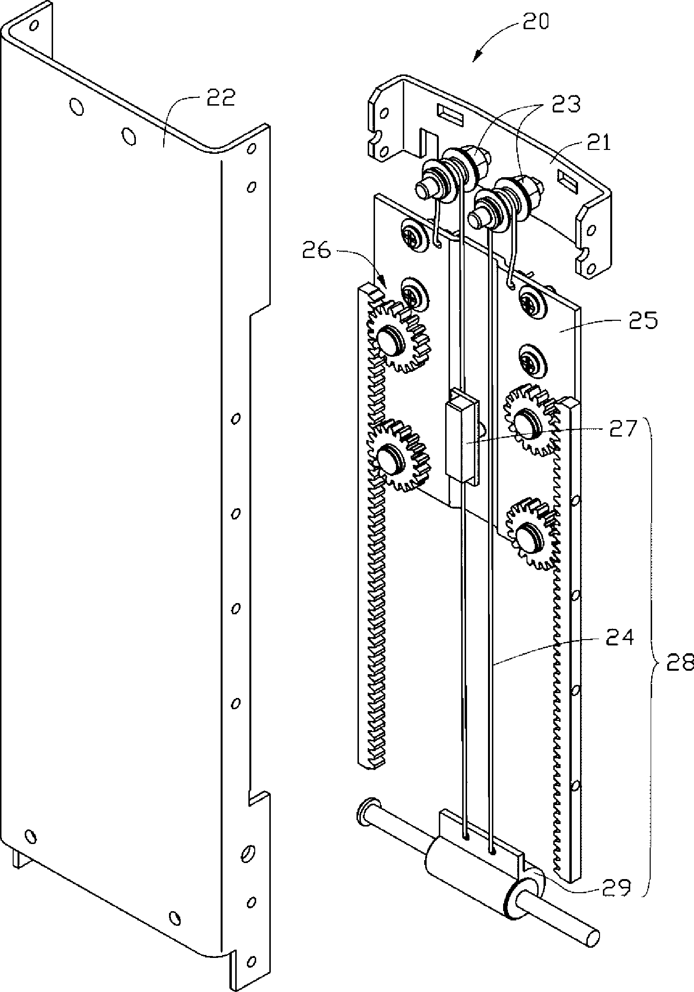
[0015] see image 3 , The lifting mechanism 20 described in this preferred embodiment includes a fixed frame 21 , a bracket 22 , two roller assemblies 23 , a sliding plate 25 , a transmission assembly 26 and a gravity balance device 28 .

[0016] Please also see Figure 4 , the fixing frame 21 includes a rectangular backboard 212 and two side baffles 214 formed by extending from two opposite sides of the backboard 212 perpendicular to the backboa...


PUM


Abstract

The invention provides an elevator mechanism, which comprises a bracket, a sliding panel, two roller components, a transmission component and a gravity balance device. The roller components comprise two rollers which are rotatably arranged on the roller components. The transmission component comprises two racks and at least two gears. The two racks are symmetrically arranged on the bracket. The at least two racks are arranged on the sliding panel and meshed with the rack in a rolling way. The gravity balance device comprises a guy rope and a coil spring. The guy rope is connected with the coil spring, bypasses the roller and is connected with the sliding panel. The coil spring is rotatably connected with the bracket. The invention provides the elevator mechanism with compact structure, low cost and better stability.

Description

technical field [0001] The invention relates to a lifting mechanism, in particular to a lifting mechanism of a liquid crystal display. Background technique [0002] Compared with CRT (Cathode Ray Tube, cathode ray tube) displays, liquid crystal display devices have the advantages of small size and light weight, and now they have gradually replaced traditional CRT displays and become mainstream products in the market. However, in the existing liquid crystal display lifting mechanisms, most of them realize the lifting function with a slide rail structure. [0003] Such as figure 1 As shown, a conventional lifting mechanism for adjusting the height of a liquid crystal display includes: a lifting seat 5 , a lifting block 6 and a coil spring 7 . A groove 51 is defined on the lifting base 5 , and two opposite sliding rails 52 are arranged in the groove 51 , and a fixing hole 53 is formed on the top of the outer edge of the groove 51 . The lifting block 6 is accommodated in the ...

Claims


Application Information

Patent Timeline
Patent Type & Authority Applications(China)
IPC IPC(8): F16M11/04F16M11/20G06F1/16
CPCF16M11/2021F16M2200/028F16M11/10F16M11/105F16M11/04F16M11/24Y10S248/917
Inventor 甘文林王铁柱
Owner HONG FU JIN PRECISION IND (SHENZHEN) CO LTD
Learn More