Spare brake beam having replaceable brake heads

A technology of brake beams and brake shoe holders, which is applied to railway braking systems, operating mechanisms of railway vehicle brakes, railway car body parts, etc., and can solve problems such as difficulty in disassembling damaged brake shoe holders

Active Publication Date: 2009-07-15
STUCKI DE MEXICO S DE R L DE C V
View PDF0 Cites 0 Cited by
  • Summary
  • Abstract
  • Description
  • Claims
  • Application Information

AI Technical Summary

Problems solved by technology

[0015] For brake beams with bolted shoe supports, if it is necessary to replace the worn brake shoe support, simply removing the damaged brake shoe support is as very difficult

Method used


Image

  • Spare brake beam having replaceable brake heads
  • Spare brake beam having replaceable brake heads
  • Spare brake beam having replaceable brake heads

Examples


Embodiment Construction

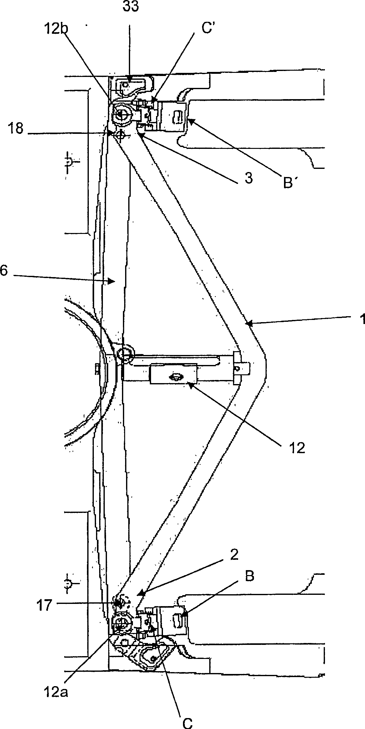
[0038] The brake beam of the present invention will now be described in detail with reference to a common brake beam according to the most general embodiment of the present invention shown in the drawings, in which the same reference numerals denote the same parts in the drawings, The brake beam of the present invention includes:

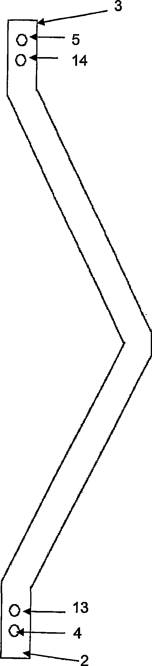
[0039] A "V"-shaped tension member 1 having a first end 2 and a second end 3, the "V"-shaped tension member 1 has a groove-shaped cross section (not shown), which includes a bottom wall and two upward The protruding side walls, each hanging on the edge of the bottom wall, and including a first pair of opposite holes 4 and a second pair of opposite holes 5, each hole is located opposite to each other in the opposite side wall, each pair of holes are located in the receiving Near the ends 4 and 5 of the pulling member 1;

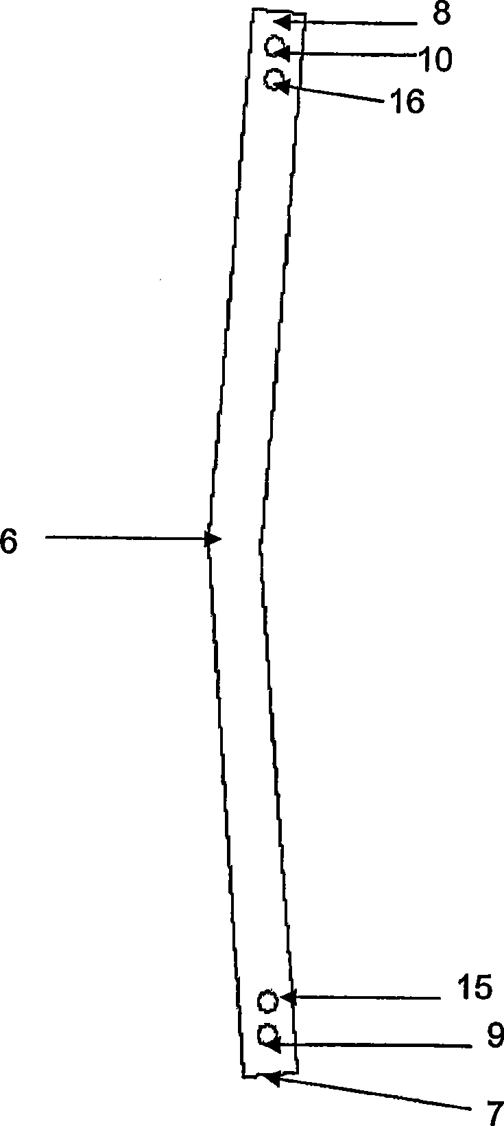
[0040] A compression member 6 having a first end 7 and a second end 8, the first end 7 and the second end 8 are consistent with the fi...


PUM


Abstract

A brake beam including means for allowing the brake head to be replaced without effort and to include replaceable brake heads (B, B').

Description

Technical field [0001] The present invention relates to a brake beam used in a train carriage, and in particular, to a brake beam that can be quickly installed and its brake shoe support can be quickly replaced when needed. Background technique [0002] As we all know, the train carriage is equipped with a brake head assembly, which presses the brake shoe against the wheel to slow the wheel or stop the carriage. [0003] Generally speaking, the brake shoe support assembly is fixed on a structure called "brake beam", which is installed laterally in the bogie of the car and connected to the lever. The brake shoe can be pressed against the wheel by applying force to the lever. on. [0004] The brake beam usually includes a substantially "V"-shaped tension member, a compression member whose end is connected to the end of the tension member, a brake shoe support subassembly connected to each end of the compression member, and two end extensions , And struts, wherein each end extension...

Claims


Application Information

Patent Timeline
Patent Type & Authority Applications(China)
IPC IPC(8): B61H13/36
CPCB61H13/36
Inventor J·德拉福恩特法力亚斯
Owner STUCKI DE MEXICO S DE R L DE C V
Why Eureka
Try Eureka