
Punching machine and punching method thereof for printed circuit board

A technology of printed circuit boards and punching machines, which is applied in manipulators, manufacturing tools, metal processing, etc. It can solve the problems of large mobile frame area, inconvenient clamping, and reduced speed, so as to achieve small motion inertia and low maintenance costs. Low, the effect of improving stability

Inactive Publication Date: 2009-07-15
宁波三盾电子科技有限公司
View PDF5 Cites 13 Cited by
  • Summary
  • Abstract
  • Description
  • Claims
  • Application Information

AI Technical Summary

Problems solved by technology

[0006] The fully automatic positioning punching machine of Taiwan Fiber Optic adopts the working method that the machine head does not move, and a single mobile manipulator clamps the object to be punched for large-scale and high-precision movement. However, the mobile frame area is relatively large, the rigidity is poor, and the movement process trembles. In order to improve the punching accuracy can only reduce the speed
Therefore, although the price of optical fiber equipment in Taiwan is lower than that of Yamaha, the speed is also slower at 0.62 seconds / hole, and the clamping is very inconvenient

Method used


Image

  • Punching machine and punching method thereof for printed circuit board
  • Punching machine and punching method thereof for printed circuit board
  • Punching machine and punching method thereof for printed circuit board

Examples


Embodiment

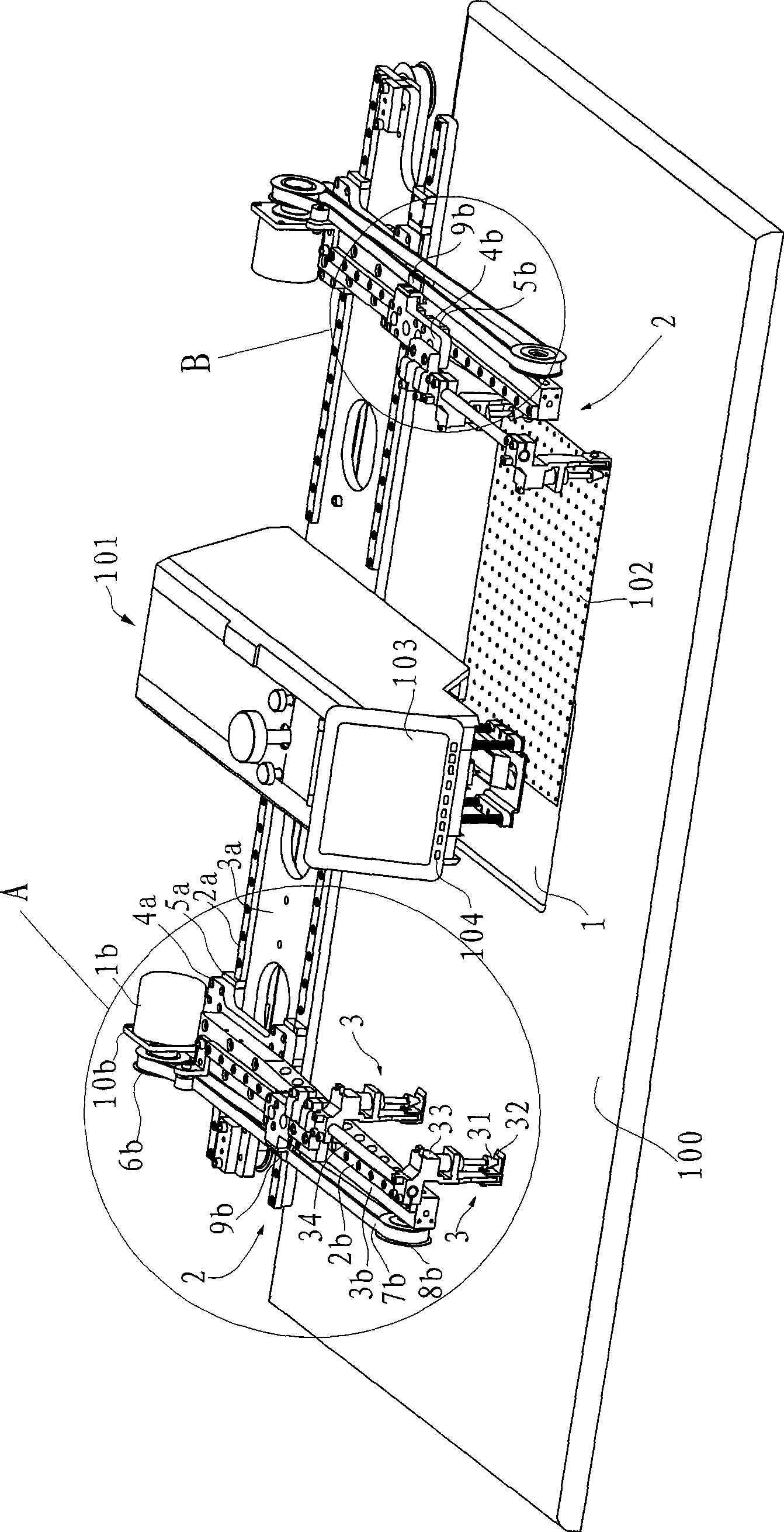
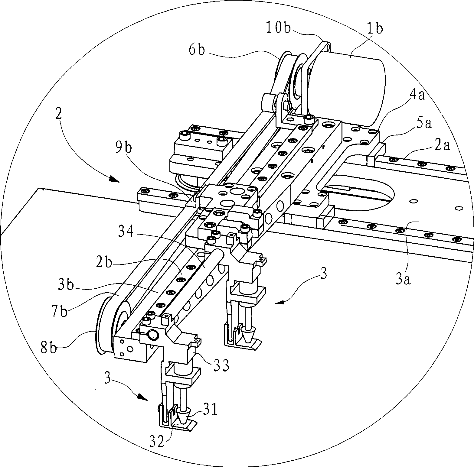
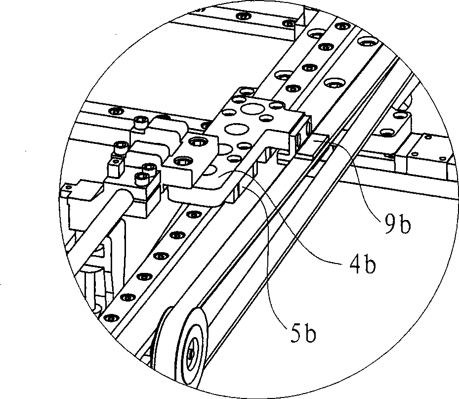
[0053] Example: as Figure 1 to Figure 4 As shown, the printed circuit board punching machine in this embodiment includes a machine head 101, a worktable 100, a mobile table 1, a control device (not shown in the figure) and a mobile manipulator 2, and the machine head 101 is provided with punching holes The mechanism, the pressing device, the display panel 103 and the input button 104, the punching mechanism is used to punch holes on the printed circuit board 102, in this embodiment, the punch 9 and the concave mould structure are used. The pressing device can press the printed circuit board 102 against the mobile table 1 to make the printed circuit board 102 move with the mobile table 1 . In this embodiment, a presser foot 4 is used.

[0054] The moving table 1 is used for fine-tuning the position of the printed circuit board 102 in a small range, and is located in the center of the work table 100, and has a transverse driving mechanism and a longitudinal driving mechanism (b...


PUM


Abstract

The invention relates to a punching machine for a printed circuit board, which comprises a punching mechanism, clamping devices and a camera device. The punching machine for a printed circuit board is characterized by further comprising two mobile manipulators which are respectively arranged at two sides of the punching mechanism; each mobile manipulator is provided with a longitudinal mobile mechanism, a transverse mobile mechanism and the clamping device for clamping a printed circuit board; and a control device is used for analyzing and processing the obtained data based on the images transmitted by the camera device, driving the punching mechanism and the camera device according to a program and driving the mobile manipulators to complete the handover of the printed circuit board at a reasonable position. The invention further discloses a punching method of the punching machine for a printed circuit board. Compared with the prior art, the invention has the advantages that the punching speed is improved; the moving inertia of the whole operation of completing the handover between the two mobile manipulators according to the reasonable position calculated by the control device is small, and the large-range high-precision movement needed by a single manipulator is not required; and the stability and reliability of the device and the precision of punching are improved.

Description

technical field [0001] The invention relates to a printed circuit board punching machine, and the invention also discloses a punching method of the printed circuit board punching machine. Background technique [0002] Printed circuit board punching machine (also known as punching machine or punching machine) is an indispensable processing equipment in the process of manufacturing circuit boards. Its work efficiency and processing accuracy directly affect the entire process of manufacturing circuit boards. Common The printed circuit board punching machine includes a punching mechanism, a pressing device, a camera device, and a computer control device. The punching mechanism is used to punch holes on the printed circuit board; the pressing device can compress the printed circuit board; the camera The device is used to take the image of the printed circuit board, and the computer control device is used to control the whole punching work. For documents in this regard, you can r...

Claims


Application Information

Patent Timeline
Patent Type & Authority Applications(China)
IPC IPC(8): B26D1/00B25J1/00
Inventor 林永良
Owner 宁波三盾电子科技有限公司
Learn More