
The golf club using moving ball

A technology for golf clubs and golf balls, applied to golf balls, golf clubs, rackets, etc., which can solve problems such as unrecognizable swing speeds and metal balls that cannot collide with each other, and achieve the effect of enhancing the effect of practice

Inactive Publication Date: 2009-07-08
朴善爱
View PDF0 Cites 1 Cited by
  • Summary
  • Abstract
  • Description
  • Claims
  • Application Information

AI Technical Summary

Problems solved by technology

[0013] However, due to the above-mentioned device, there is such a problem that the metal balls cannot collide with each other or the two metal balls in a certain section do not collide, and the swing practice must rely on the collision of the two metal balls to complete, thus causing swing Rod speed not recognized

Method used


Image

  • The golf club using moving ball
  • The golf club using moving ball
  • The golf club using moving ball

Examples


Embodiment approach

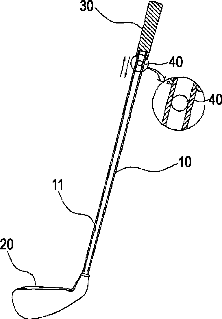
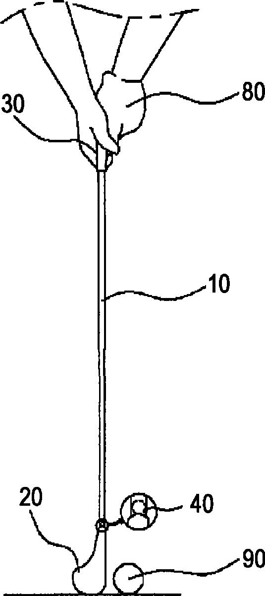
[0062] The structure of the present invention comprises: rod 10, is formed with the moving channel 11 of uniform width along the length direction on its inner side or outer side, is also provided with partition wall 60 on moving channel 11, and described partition wall 60 divides moving channel 11 into multiple sections; handle 30, arranged on the top of the shaft 10, for grasping by the hand 80; the club head 20, arranged at the bottom end of the shaft 10, for hitting the golf ball 90; and the moving ball 40, arranged on the inner side or The outer side can move along the moving channel 11.

[0063] The above-mentioned structure not only allows the moving ball 40 to emit a continuous impact sound similar to "click" due to the partition wall 60, but also can generate vibration when the moving ball 40 moves in the rod 10.

specific Embodiment approach

[0065] Below, the present invention will be described in detail in conjunction with the accompanying drawings having the technical solutions of the present invention.

Embodiment approach 1

[0067]The golf club in Embodiment 1 includes: a shaft 10, which is provided with a moving channel 11 with a uniform width along the length direction inside or outside; a handle 30, which is arranged on the top of the shaft 10, for the user to grasp with his hand 80; The head 20 is provided at the bottom end of the shaft 10 to hit the golf ball 90 ; and the moving ball 40 is provided with inner and outer sides of the moving passage 11 and can move along the moving passage 11 in the shaft 10 .

[0068] In the present structure, the moving passage 11 is formed inside the rod 10 in the lengthwise direction.

[0069] It is suggested that the shaft 10 is preferably made of a lightweight material, the same material and weight as a conventional golf club shaft 10 . The inner side of the rod 10 is preferably made of a lightweight material such as stainless steel, titanium alloy or aluminum alloy.

[0070] Commonly used rods 10 have different types, some have uniform thickness from top...


PUM


Abstract

This invention is concerning about the golf club for backswing practice. The golf club for backswing practice of this invention is composed of a shaft with moving passage in the direction of length to the inside or outside, grip which is installed at the top of shaft and hold with hands, head which is installed at the bottom of shaft and hit the ball and moving ball which is made to be able to move inside along with moving passage and is installed in the inside and outside of moving passage of the shaft. For this invention, the incorrect swing posture or speed can be corrected easily through vibration occurred by the movement of moving ball which moves on shaft of golf club.

Description

technical field [0001] The present invention relates to a golf club utilizing a moving ball. Background technique [0002] Generally speaking, the golf swing posture is divided into address→backswing→top of the back swing→down swing→impact→ Send rod (follow through) → close rod (finish). [0003] Especially when hitting or teeing off to drive a golf ball a long distance, it is necessary to swing the golf club up over the shoulder and then swing the club hard to hit the golf ball. [0004] At this time, although the driving distance of the golf ball depends on the swing speed and power of the golf club, it mainly depends on the position of the back swing. Therefore, in order to send the golf ball far, the posture and speed of the back swing are particularly important. [0005] As a device for correcting the posture and speed of the back swing, Korean Registered Patent No. 10-0293018 of the same family discloses a "back swing height indicating device" that uses golf ball i...

Claims


Application Information

Patent Timeline
Patent Type & Authority Applications(China)
IPC IPC(8): A63B53/00
CPCA63B60/04A63B69/3638A63B2053/0495
Inventor 朴善爱
Owner 朴善爱
Learn More