Rotational flow precipitator with adjustable input air

An adjustable dust collector technology, which is applied in the direction of swirl devices and devices whose axial direction can be reversed, can solve the problems of large movement resistance, easy damage, loss of energy saving and other problems, and achieve reduction The effect of power, simplified structure and convenient installation

Active Publication Date: 2009-07-08
JIANGSU XINHUANENG ENVIRONMENTAL ENG CO LTD
View PDF5 Cites 25 Cited by
  • Summary
  • Abstract
  • Description
  • Claims
  • Application Information

AI Technical Summary

Problems solved by technology

Obviously, the structure of the above-mentioned CN2481419Y cannot meet the aforementioned requirements and often shows that all cyclones are in an indiscriminate all-purpose state
[0004] In view of the above, the Chinese utility model patent authorization announcement number CN201154329Y discloses an air volume regulating device for a cyclone dust collector (applied by the applicant), from lines 1 to 9 on page 2 of the specification of the patent and in combination with the patent figure 1 and figure 2 It can be seen that the air volume adjustment of the cyclone of the cyclone dust collector can be realized, but the overall structure is relatively complicated, and it also leads to an unreasonable increase in the volume of the dust removal box. In particular, the movable plate of the patent is the opening and closing cover. The movement mode is a drawer-type movement mode, and friction will be generated during each opening and closing process, which will easily damage the movable plate, and the movement resistance is large, the power of the power mechanism is large, and energy saving is lost

Method used


Image

  • Rotational flow precipitator with adjustable input air
  • Rotational flow precipitator with adjustable input air

Examples


Embodiment Construction

[0019] In order to enable the examiners of the patent office, especially the public, to understand the technical essence and beneficial effects of the present invention more clearly, the applicant will describe in detail below in conjunction with the accompanying drawings in the form of embodiments, but none of the descriptions of the embodiments is a description of the present invention. Restriction of the inventive solution, any equivalent transformation made according to the concept of the present invention which is only in form but not in substance shall be regarded as the scope of the technical solution of the present invention.

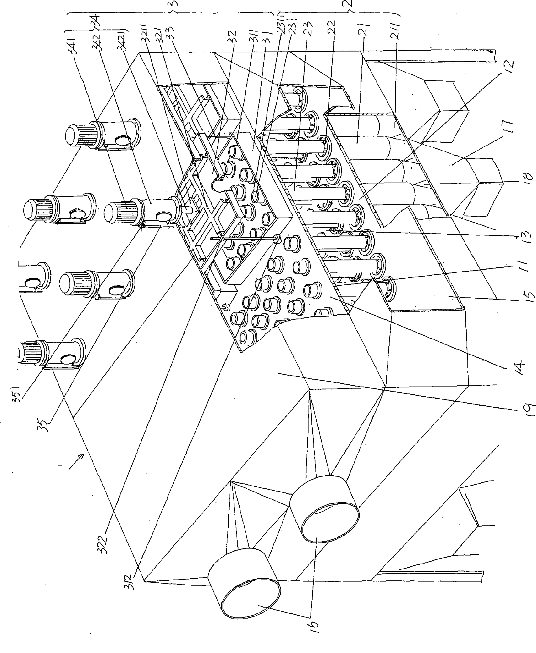
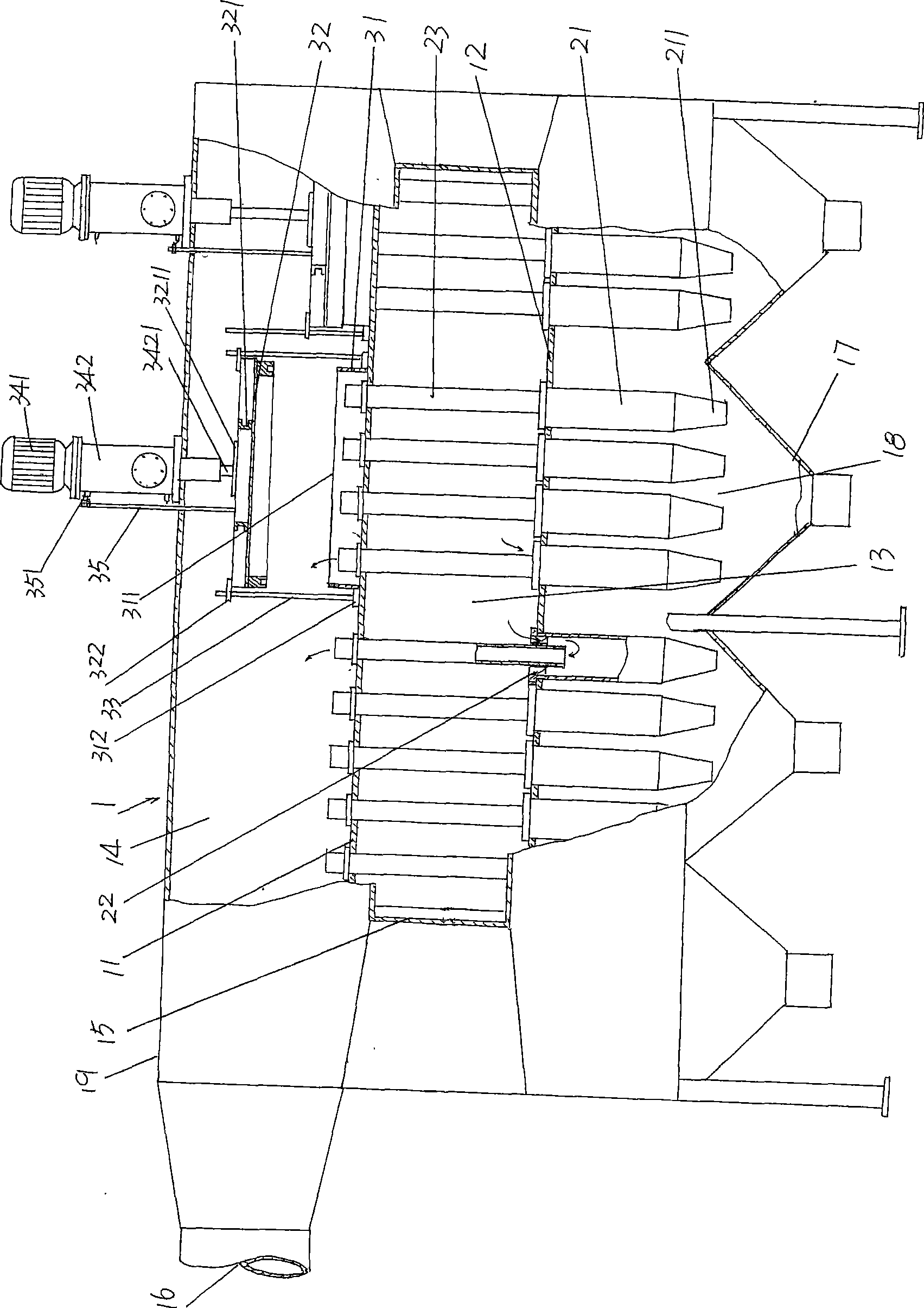
[0020] please see figure 1 and figure 2 , the dust removal box body 1 whose size or specification is not limited by the illustration is given. The dust removal box body 1 is divided into three chambers by the upper and lower supporting plates 11, 12, namely the upper return air chamber 14 , the air inlet cavity 13 in the middle and the lower b...


PUM


Abstract

The invention relates to a cyclone dust collector with adjustable air volume, belonging to the technical field of smoke gas dust collection devices. The cyclone dust collector comprises a dust collection box body, a group of cyclones and at least one set of device for adjusting the air volume of each cyclone, wherein the interior of the dust collection box body is divided into an air inlet cavity, an air return cavity and a lower box cavity by an upper support and a lower support, an air inlet interface and an air return interface are formed on the lateral part of the dust collection box body, the air inlet interface is communicated with the air inlet cavity, the air return interface is communicated with the air return cavity, and the bottom of the dust collection box body is extended to form a duct discharge hopper; each cyclone comprises a turboseparator, a gate apparatus and an air guide pipe; and the device for adjusting the air volume of each cyclone comprises coffers used for enclosing and isolating each cyclone, an opening and closing cover, a guide rod and a driving mechanism for the opening and closing cover. The cyclone dust collector has the advantages of simplified structure, reduced integral volume of the dust collection box body of the cyclone dust collector and convenient installation, is in favor of the protection of the opening and closing cover, and exemplifies energy saving.

Description

technical field [0001] The invention belongs to the technical field of flue gas dedusting devices, and specifically relates to a cyclone dust collector with adjustable air volume, which is applied in the iron and steel industry such as coking plants for dust removal of coke CDQ flue gas, and sintering machine heads and tails of sintering plants. Dust removal from waste gas and flue gas from rotary kiln or shaft furnace with pellet grate, even suitable for dust removal of fly ash collected in power plants. Background technique [0002] As known in the industry, the cyclone dust collector is also called the cyclone dust collector, which is composed of dozens, hundreds or even thousands of cyclones installed in the dust removal box. The cyclone on the lower supporting plate in the box body and the guide (also known as centrifugal guide vane) placed on the cyclone and the lower end mated on the guide extend into the cyclone while the upper end penetrates into the dust box body ...

Claims


Application Information

Patent Timeline
Patent Type & Authority Applications(China)
IPC IPC(8): B04C5/28B04C11/00
Inventor 赵克宇
Owner JIANGSU XINHUANENG ENVIRONMENTAL ENG CO LTD
Why Eureka
Try Eureka