Modular electric protection device comprising an additional electric function such as the differential protection function

A technology of protection unit and function, which is applied to parts, electrical components, protection switches, etc. of protection switches, and can solve problems such as not being able to be used as installation units

Active Publication Date: 2009-06-24
SCHNEIDER ELECTRIC IND SAS
View PDF6 Cites 6 Cited by
  • Summary
  • Abstract
  • Description
  • Claims
  • Application Information

AI Technical Summary

Problems solved by technology

In this case, the gap below or above cannot be used as a mounting unit

Method used


Image

  • Modular electric protection device comprising an additional electric function such as the differential protection function
  • Modular electric protection device comprising an additional electric function such as the differential protection function
  • Modular electric protection device comprising an additional electric function such as the differential protection function

Examples


Embodiment Construction

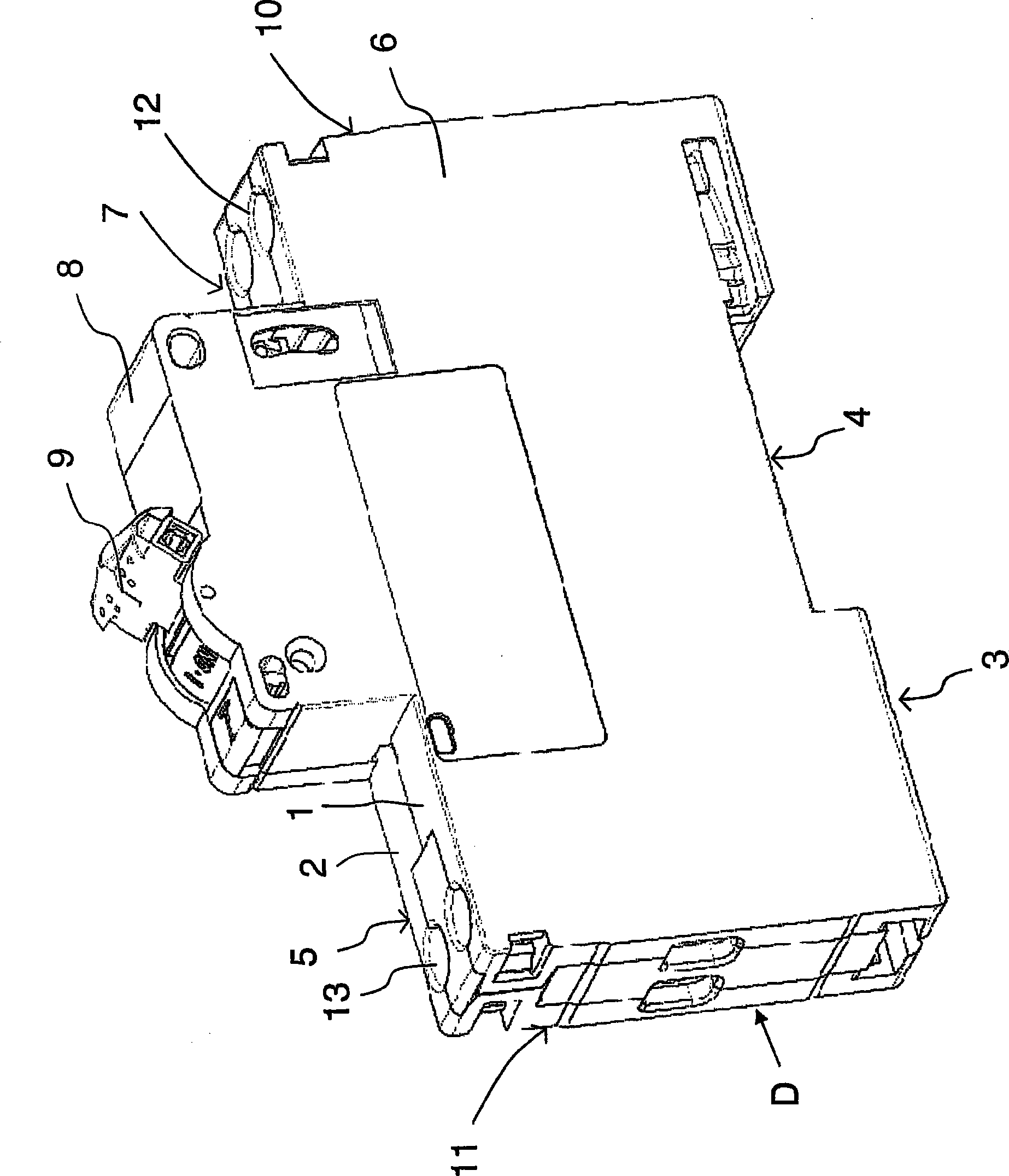
[0044] figure 1 A phase / neutral differential circuit breaker D is shown in , arranged in a module housing with a width of 18 mm and comprising two parts 1, 2, a part 1 designed to perform electrical phase breaking and a part designed to perform neutral breaking Part 2. The housing has a rear panel 3 including a mounting rail 16 for fixing to the figure 2) of the recess 4; two main panels 5, 6 through which the housing can be joined to other housings of the same type; a front panel 7 comprising a raised portion 8 comprising Manual operation of the unit 9; top 10 and bottom 11 with line-side terminals 12 respectively for connecting the unit to a power supply and for connecting the unit to a load side other than the unit The load-side terminal 13 of the unit.

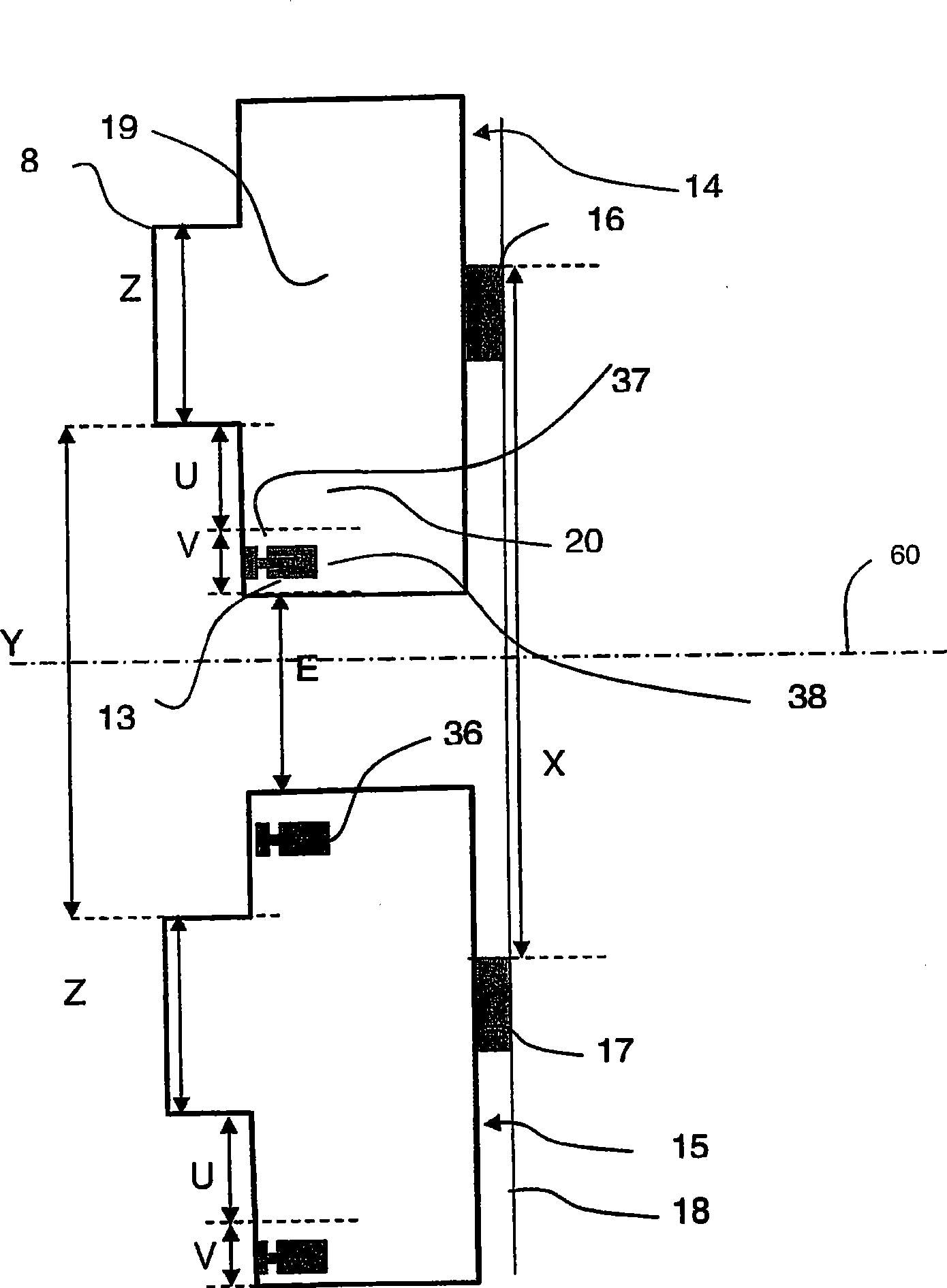
[0045] exist figure 2 In FIG. 2 , two units 14 , 15 are shown mounted respectively on mounting rails 16 , 17 fixed one above the other on a support surface 18 .

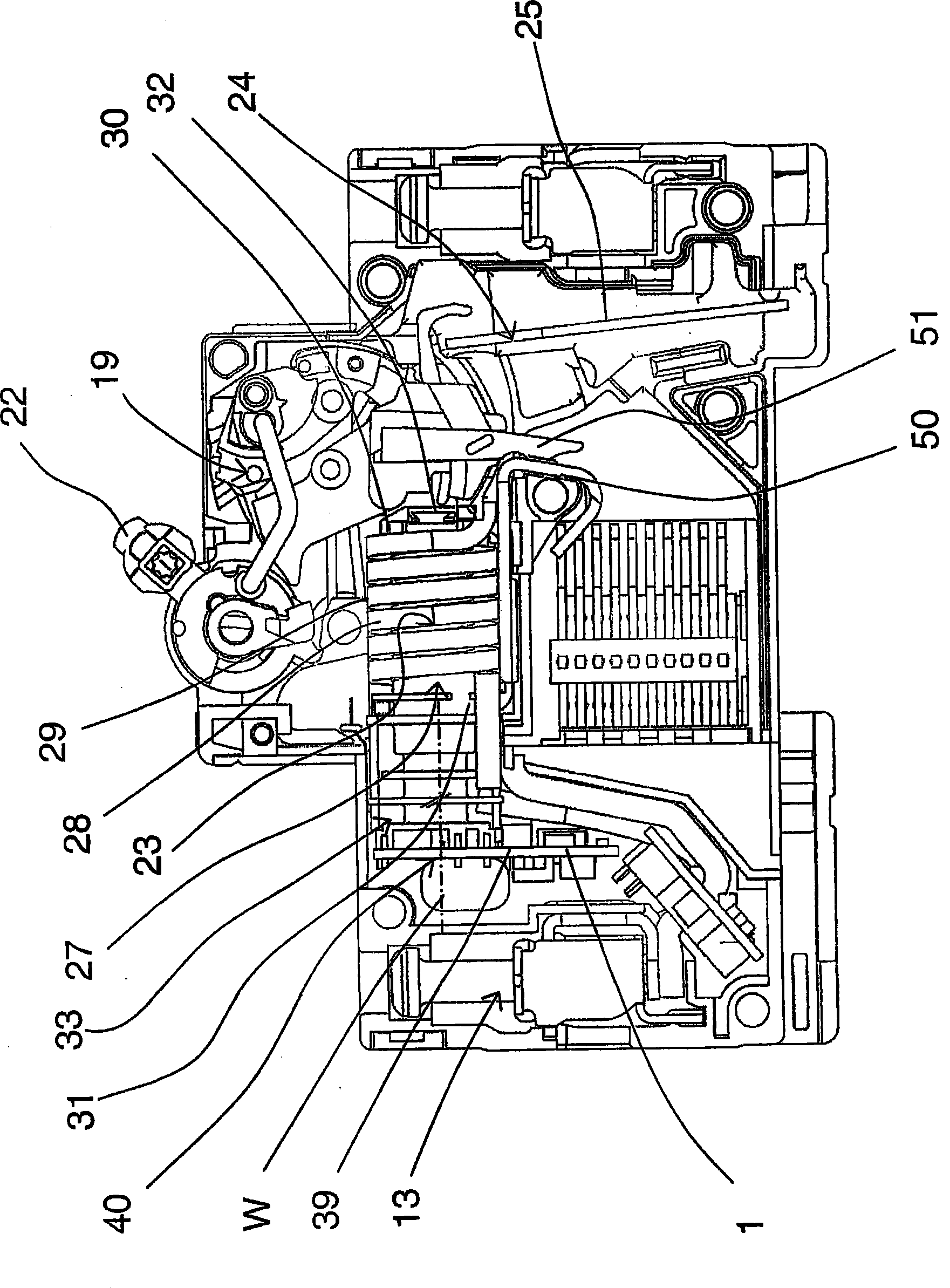
[0046] exist image 3 and 4 , it can be seen that ...


PUM


Abstract

The invention relates to a modular electric protection unit. The height of the unit is increased comparing with a standard height of the unit, thereby forming an additional volume (20) between a mechanism (19) and a terminal. The additional volume (20) is designed a member with a complementary electrical function. The maximum height U of the additional volume (20) is (((X-Z) / 2) / 3 / 4)-V, wherein the Z is a height of a nose (8) of the unit, the V is a height of a housing (38) of the terminal (13), the X is the minimum distance standardized between two rails, these heights are measured parallel to the rear surface of the apparatuses and perpendicularly with the longitudinal direction of rails.

Description

technical field [0001] The invention relates to a modular electrical protection unit comprising at least one module, each module arranged in a substantially parallelepiped-shaped housing, said housing comprising means for fixing to a mounting rail, called a first rail a rear panel, a front panel comprising a raised portion and a manually operated device accommodating the unit, said housing comprising a line-side terminal at one end thereof and a load-side terminal at an opposite end thereof, and between these line-side and load-side terminals housing unit mechanism, the unit also includes a supplementary electrical function, such as a differential function, the unit can be arranged above or below the same unit fixed to the second track, the second track is generally in the same position as the first track extending in a plane and parallel to the first rail, the two rails being separated by a standard minimum distance. Background technique [0002] Differential circuit break...

Claims


Application Information

Patent Timeline
IPC IPC(8): H01H71/24H01H71/02H01H71/08H01H83/14
CPCH01H71/0207H01H71/0271H01H83/226H01H71/025
Inventor 伯纳德·勒博杰罗姆·穆尼尔卡勒斯西蒙·蒂安
Owner SCHNEIDER ELECTRIC IND SAS
Why Eureka
Try Eureka