Automatic telescopic foot pedal apparatus of vehicle
An automatic telescopic and vehicle technology, which is applied in the layout, transportation and packaging of vehicle components, pedals or ladders, can solve the problems of complex structure of automatic telescopic pedals, control the telescopic distance of pedals, and easy occurrence of accidental failures, and achieves aesthetics, The effect of flexible operation and reasonable structure of the organization
- Summary
- Abstract
- Description
- Claims
- Application Information
AI Technical Summary
Problems solved by technology
Method used
Image
Examples
Embodiment 1
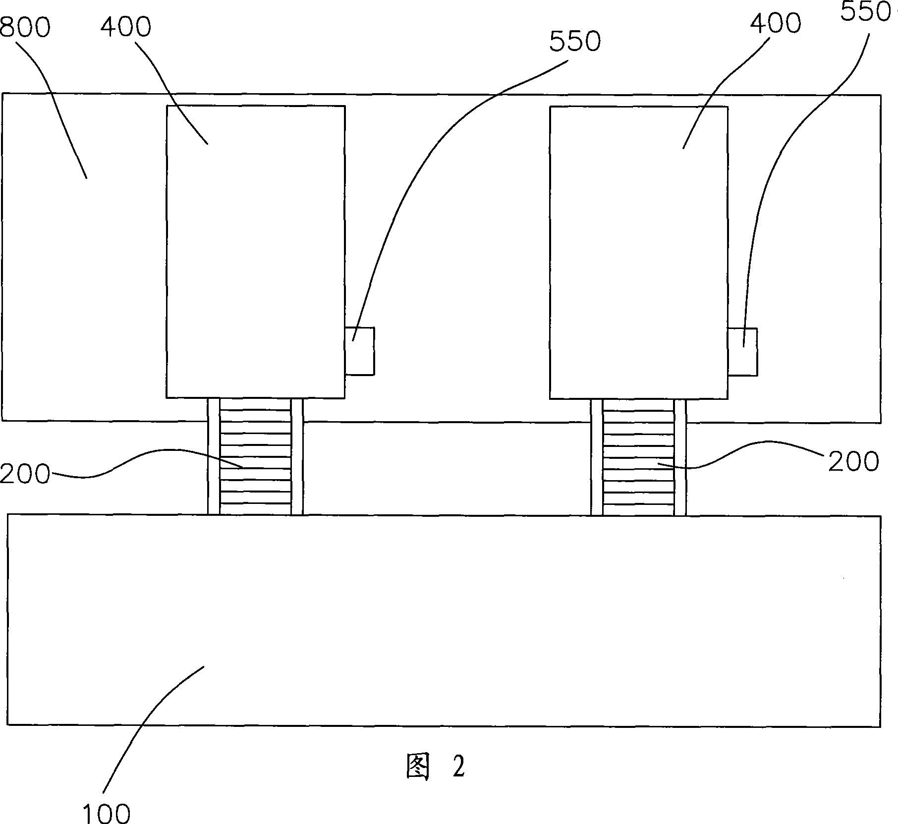
[0040] Please also refer to Figure 1 to Figure 11 , the vehicle automatic retractable pedal device of the present invention includes a pedal 100, a pair of telescopic mechanisms connected between the pedal 100 and the frame 800, and a control system for controlling the movement of the pair of telescopic mechanisms.
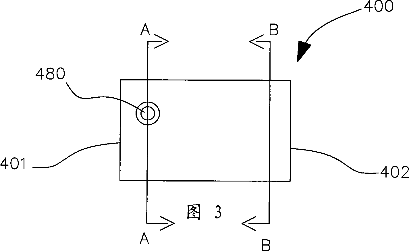
[0041] Each telescoping mechanism includes a main casing 400 fixed on the vehicle frame 800, a transmission gear 500 pivotally arranged in the main casing 400, and a driving device (not shown, In this embodiment, it is a motor), the telescopic rod 200 that can move relative to the main housing 400 , and the limit plate 700 used to limit the movement position of the telescopic rod 200 .
[0042] Wherein, the main housing 400 is provided with a guide groove 420 and a receiving groove 410 . The telescopic rod 200 is slidably disposed in the guide groove 420 . The transmission gear 500 is pivotally disposed in the receiving groove 410 . Two pivot holes 480 for piv...
Embodiment 2
[0050] As another kind of scheme of the present invention, other parts are identical with embodiment 1, and difference is:
[0051] Balls or bearings are embedded in the bottom of the telescopic rod 200 .
[0052] A telescopic protective cover (not shown) is further provided on the outside of the telescopic rod 200, which can be extended or shortened with the advancement or retreat of the first connecting end 230 of the telescopic rod 200 to protect the rack portion 222 from damage.
[0053] An anti-skid plate or an anti-skid sleeve (not shown) is further provided on the pedal 100 .
[0054] It further includes a sleeve (not shown) for covering on the outside of the main housing 400 for protection.
[0055] It further includes a connecting piece (not shown) that is welded or screwed on the vehicle frame 800. After other parts of the vehicle automatic retractable pedal device of the present invention are assembled, they are directly connected to the connecting piece, so as to...
Embodiment 3
[0058] As another kind of scheme of the present invention, other parts are identical with embodiment 1, and difference is:
[0059] In this embodiment, three telescopic mechanisms are adopted, and the first connection ends 230 of the three telescopic rods 200 are respectively connected with the front section, the middle section, and the rear section of the pedal 100 .
[0060] In this embodiment, the receiving groove 410 is located below the guiding groove 420 and communicates with it.
[0061] The matching assembly 550 includes an external gear (not shown in the figure), and the gear of the motor is engaged with the external gear for transmission.
PUM
 Abstract
Description
Claims
Application Information
 - R&D Engineer
- R&D Manager
- IP Professional
- Industry Leading Data Capabilities
- Powerful AI technology
- Patent DNA Extraction
Browse by: Latest US Patents, China's latest patents, Technical Efficacy Thesaurus, Application Domain, Technology Topic, Popular Technical Reports.
© 2024 PatSnap. All rights reserved.Legal|Privacy policy|Modern Slavery Act Transparency Statement|Sitemap|About US| Contact US: help@patsnap.com


