
Method for feeding hydraulic fluid and coolant and lubricant for wet operation clutch of gear box

A hydraulic fluid, clutch technology, applied in the direction of clutch, friction clutch, mechanical drive clutch, etc., to achieve the effect of saving axial structure space

Inactive Publication Date: 2009-06-17
ZF FRIEDRICHSHAFEN AG
View PDF1 Cites 4 Cited by
  • Summary
  • Abstract
  • Description
  • Claims
  • Application Information

AI Technical Summary

Problems solved by technology

Other configurations and advantages are derived from dependent rights

Method used


Image

  • Method for feeding hydraulic fluid and coolant and lubricant for wet operation clutch of gear box
  • Method for feeding hydraulic fluid and coolant and lubricant for wet operation clutch of gear box
  • Method for feeding hydraulic fluid and coolant and lubricant for wet operation clutch of gear box

Examples


Embodiment Construction

[0018] The mode of operation and the general construction of wet-running clutches or dual clutches are well known to those skilled in the art, so that the components relevant to the invention are described below.

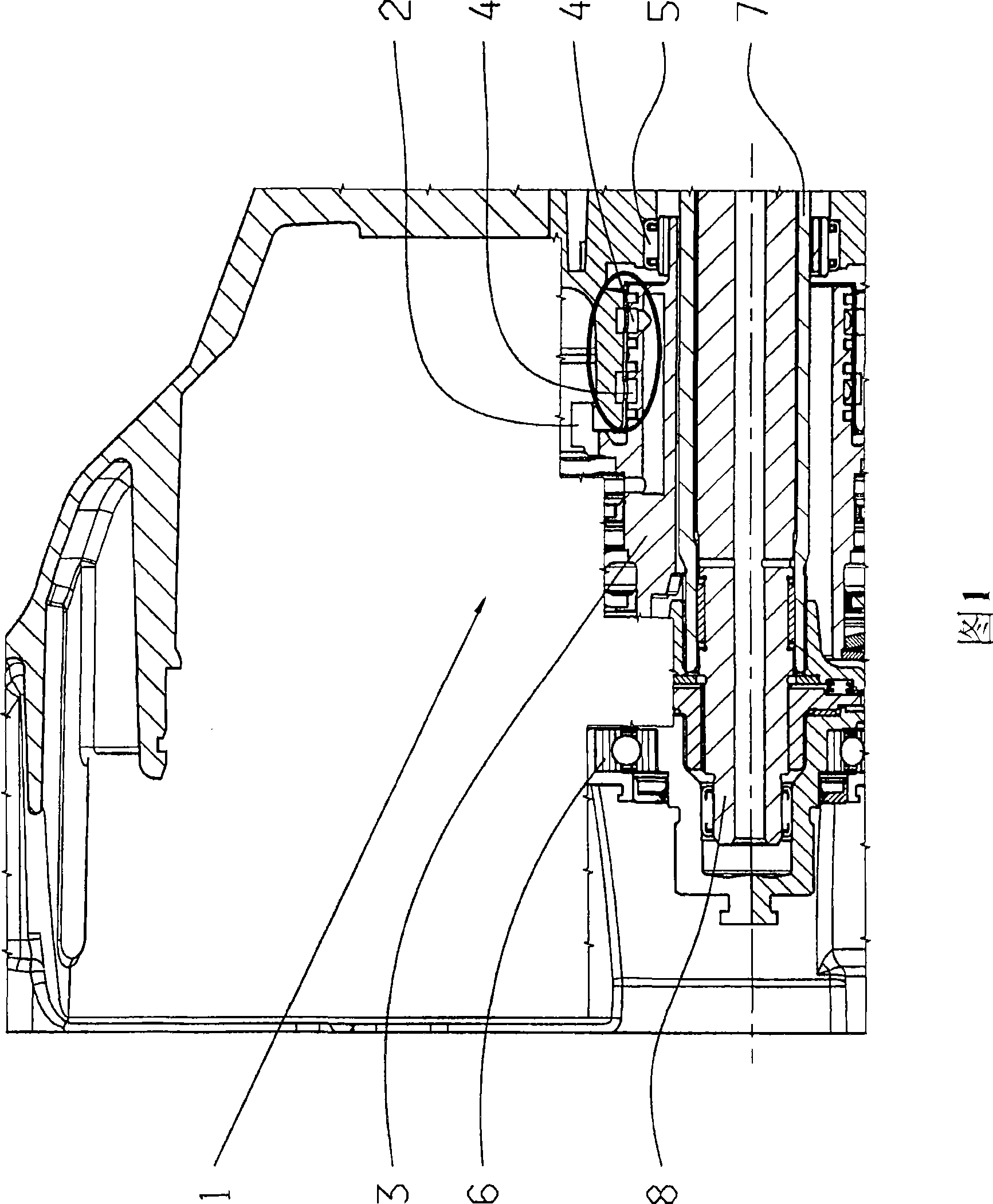
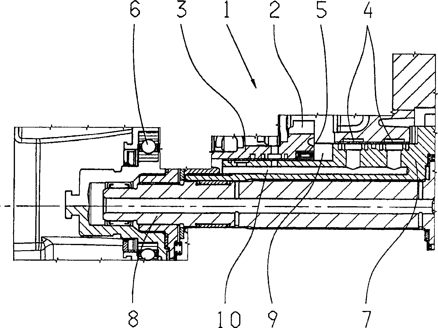
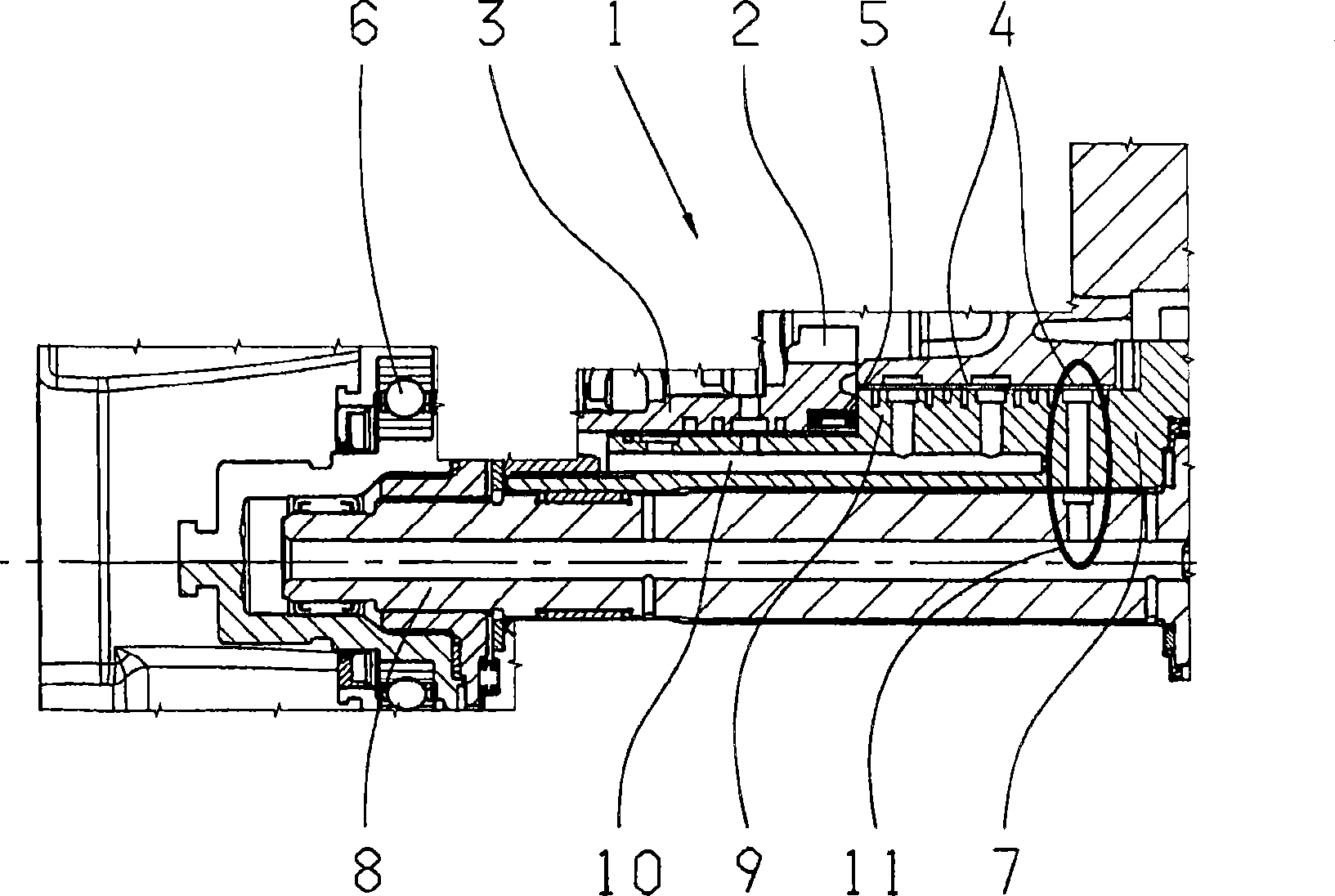
[0019] FIG. 1 shows a double clutch 1 comprising a pump transmission element designed as a pump transmission wheel 2 to which hydraulic fluid is supplied via a clutch sleeve 3 by means of a rotary converter 4 .

[0020] As can be seen from FIG. 1 , the bearing 5 for supporting the clutch is arranged axially behind the region in which the rotary converter 4 is arranged, thus disadvantageously increasing the axial construction space requirement. A further bearing 6 for supporting the clutch is arranged in front of the area in which the rotary converter 4 is accommodated, viewed in the axial direction. In addition, the outer drive shaft embodied as a hollow shaft is marked with 7 and the inner drive shaft guided by the hollow shaft 7 is marked with 8 , where each drive...


PUM


Abstract

The supply unit has hydraulic fluid or coolant and lubricant. The clutch (1) is arranged around an external drive shaft (7) conducted as hollow shaft. Cables (10) for the hydraulic fluid and deliveries (4) of the hydraulic fluid are integrated at the clutch, and the cables for coolant and lubricant and the deliveries (11) for coolant and lubricant are integrated at the clutch in the drive shaft.

Description

technical field [0001] The invention according to the preamble of claim 1 relates to a method for supplying hydraulic fluid and cooling and lubricants to wet-running clutches of a transmission with pump drive elements. Background technique [0002] In order to actuate wet-running clutches or dual clutches, according to the current state of the art, hydraulic fluid is conducted in an oil supply via a complex clutch sleeve to the clutch by means of a rotary converter. Here, the clutch is supported, viewed in the axial direction, behind the region of the oil transition piece, which disadvantageously increases the axial installation space requirement. [0003] In order to supply the lubricating coolant to the clutches, in the case of a dual-clutch gearbox, in the embodiment of the transmission, it is conducted through the entire gearbox from the countershaft to the side opposite the transmission and from there by the inner drive The shaft is then transmitted to the transmission...

Claims


Application Information

Patent Timeline
Patent Type & Authority Applications(China)
IPC IPC(8): F16D13/72F16D13/74F16H57/04
CPCF16D21/06F16D25/123F16H57/0441F16D25/12
Inventor 伯恩哈德·西克沃尔夫冈·里格尔
Owner ZF FRIEDRICHSHAFEN AG
Learn More