Mop with water injection device

A mop and mop rod technology, which is applied in the direction of cleaning carpets, floors, cleaning equipment, etc., can solve problems such as inconvenience, and achieve the effects of easy mopping, convenient use and simple structure

Inactive Publication Date: 2009-06-17
曾粤薇
View PDF0 Cites 2 Cited by
  • Summary
  • Abstract
  • Description
  • Claims
  • Application Information

AI Technical Summary

Problems solved by technology

[0002] At present, when the common mop used by people is mopping the floor, a bucket of water is placed next to it, and water is added while mopping the floor, which is inconvenient

Method used


Image

  • Mop with water injection device

Examples


Embodiment Construction

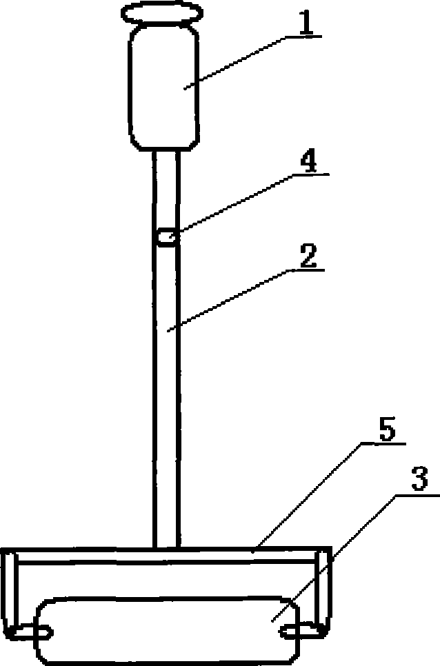
[0010] like figure 1 As shown, a mop with a water injection device includes a water storage device 1, a mop rod 2 and a mopping roller 3, the water storage device 1 is located on the top of the mop rod 2, the mop rod 2 is a hollow structure, and the outlet of the water storage device 1 The nozzle is connected to the mop rod 2 through the seepage hole 4 in the mop rod 2, and the tail end of the mop rod 2 is connected to the mopping roller 3 through the connecting rod 5, and the connecting rod 4 is a hollow structure.

[0011] Before use, first fill the water storage device 1 with water. When using it, gently pinch the water storage device 1, and the water in the water storage device 1 enters the mop rod 2 through the outlet along the water seepage hole 4 in the mop rod 2, and then passes through the Connecting rod 5 enters in the mopping cylinder 3, makes mopping cylinder 3 moist, so just can mop the floor. In the process of mopping the floor, the above operations can be repea...


PUM


Abstract

The invention discloses a mop with an injection device, comprising a water receiver, a mop rod and a mopping roller. The water receiver is positioned at the top of the mop rod that is a hollow structure. The water outlet of the water receiver is connected with the mop rod via water penetration holes inside the mop rod. The tail end of the mop rod is connected with the mopping roller via a connecting rod that is a hollow structure. The water receiver is just needed lightly pinching when mopping due to the application of the structure and the water inside the water receiver can flow inside the mopping roller through the water penetration holes and the connecting road along the mop rod so that the mopping roller keeps wet so as to have the purpose of adding water while mopping and mopping is more relaxed and convenient. The mop further has the advantages of simple structure, convenient use, etc.

Description

technical field [0001] The invention relates to a cleaning appliance, in particular to a mop with a water injection device. Background technique [0002] At present, when the common mop used by people is to mop the floor, a bucket of water is placed next to it, and water is added while mopping the floor, which is inconvenient. Contents of the invention [0003] The purpose of the present invention is to provide a mop with a water injection device, which can add water while mopping the floor, so that the mopping becomes easy and convenient. [0004] The purpose of the present invention is achieved in that a mop with a water injection device includes a water reservoir 1, a mop rod 2 and a mopping roller 3, the water reservoir 1 is located on the top of the mop rod 2, and the mop rod 2 is a hollow structure. The water outlet of the water storage device 1 is connected to the mop rod 2 through the water seepage hole 4 in the mop rod 2, and the tail end of the mop rod 2 is conn...

Claims


Application Information

Patent Timeline
IPC IPC(8): A47L13/22
Inventor 曾粤薇
Owner 曾粤薇
Why Eureka
Try Eureka