
Leakage relay

A relay and leakage detection technology, which is applied to electrical components, circuit devices, switches with multiple unbalanced current/voltage effects, etc., can solve problems such as inability to confirm zero-phase converters

Inactive Publication Date: 2011-12-28
MITSUBISHI ELECTRIC CORP
View PDF1 Cites 0 Cited by
  • Summary
  • Abstract
  • Description
  • Claims
  • Application Information

AI Technical Summary

Problems solved by technology

[0006] However, in other words, even in actual use, that is, when the leakage relay is connected to the zero-phase converter, the zero-phase converter itself cannot be confirmed by testing.

Method used


Image

  • Leakage relay
  • Leakage relay
  • Leakage relay

Examples


no. 1 Embodiment approach

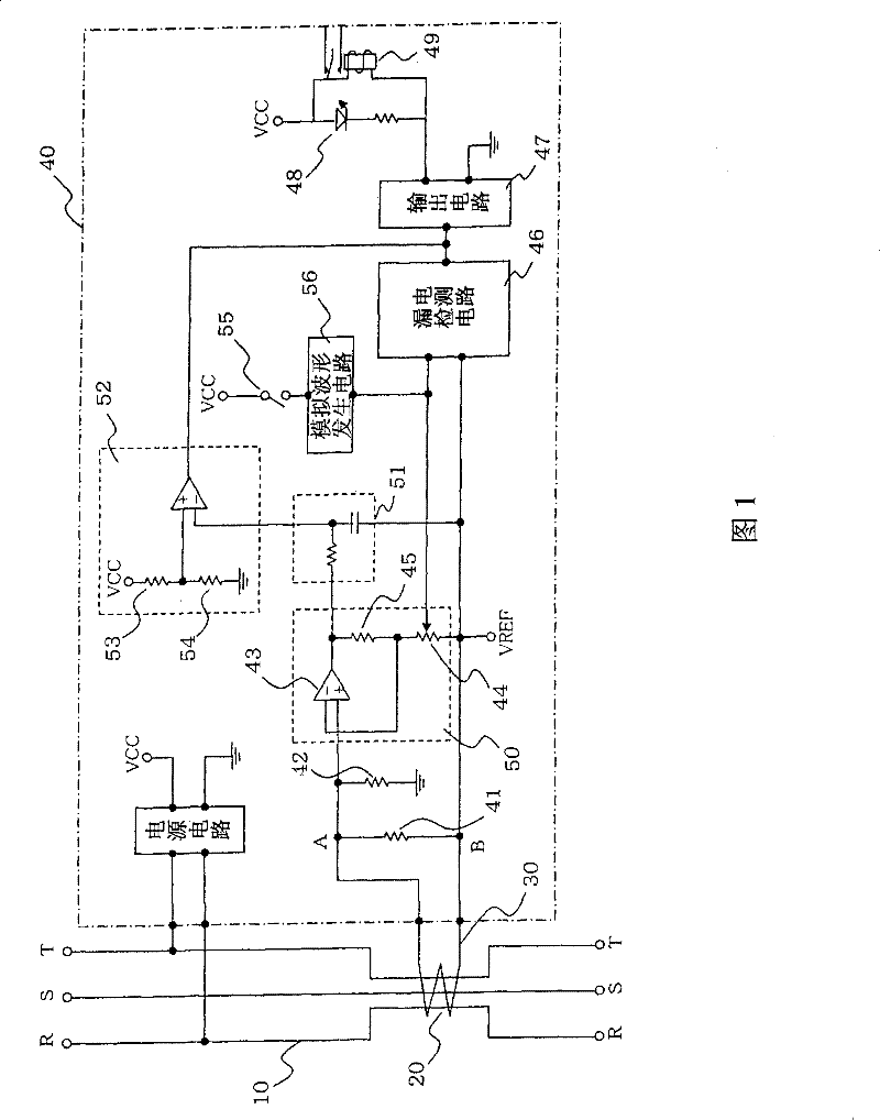
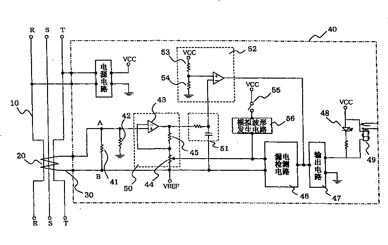
[0017] figure 1 A circuit diagram including an earth leakage relay according to the first embodiment of the present invention is shown. The output current of the zero-phase converter 20 provided on the circuit 10 of the main circuit is transformed into a voltage input by the first detection resistor 41 via the connecting lead 30 connected between the zero-phase converter 20 and the leakage relay 40 If it is input to the electric leakage detection circuit 46 and reaches the reference level, the electric leakage display LED 48 is turned on through the output circuit 47 and the electric leakage alarm output relay 49 is driven at the same time.

[0018] Here, the process of inputting the voltage obtained by the first detection resistor 41 (potential at point A in the figure) into the leakage detection circuit 46 will be described in detail. The potential at point A is input to the non-inverting input terminal of the operational amplifier 43 constituting the amplifier circuit 50 ....

no. 2 Embodiment approach

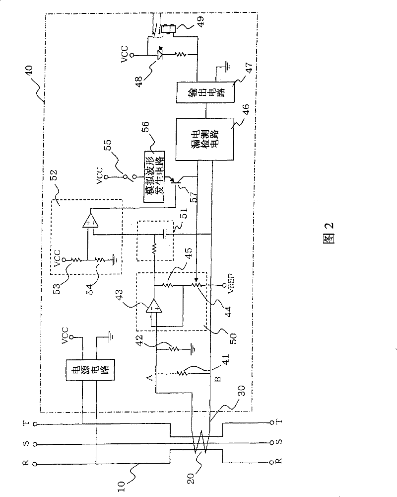
[0030]According to the first embodiment, by driving the leakage display LED 48 and the leakage alarm output relay 49 as a "disconnection alarm" at the same time as the disconnection of the connecting lead wire, there is an effect that the disconnection can be notified to the user, but in addition On the one hand, if the power supply voltage is applied to the leakage relay 40 in the temporary setting before the main circuit starts to be energized, that is, the leakage relay 40 and the zero-phase converter 20 are not connected, (this will be regarded as a disconnection) A wire break alarm is also driven. In particular, if a notification device such as a buzzer on the user side is in a connected / charged state with respect to the leakage alarm output relay 49, its influence cannot be ignored. An improvement made on this will be described as a second embodiment.

[0031] figure 2 It is a circuit diagram showing the second embodiment of the present invention.

[0032] Such as ...


PUM


Abstract

The present invention provides a leakage relay, which can perform a leakage test without winding a test coil on a zero-phase current transformer, and at the same time, can detect a disconnection or missing connection with a zero-phase current transformer without increasing the circuit scale . This leakage relay has: a first detection resistor, which converts the output current obtained by the zero-phase converter into a voltage; a leakage detection circuit, which determines the level of the voltage; an output circuit, which corresponds to the output of the leakage detection circuit, and drives The leakage display element; the analog waveform generation circuit, which generates an analog waveform based on the pressing of the test button, and the analog waveform is judged by the leakage detection circuit as being at the same level as the leakage in the main circuit; the amplifier circuit, which is interposed between the first detection Between the resistor and the leakage detection circuit, when the connecting lead wire is disconnected, the voltage obtained by dividing the voltage of the first detection resistor is input; and a comparator, which compares the signal amplified by the amplifier circuit with the reference potential, and compares the The output is input to the output circuit.

Description

technical field [0001] The present invention relates to a leakage relay, which cooperates with a zero-phase current transformer to detect the leakage of the main circuit, and outputs the occurrence of the leakage to the outside. Specifically, it relates to a device for confirming its function Improvements to the test setup. Background technique [0002] As we all know, the earth leakage circuit breaker, which is one of the circuit breakers, has a built-in leakage detection circuit, a zero-phase current transformer and an electromagnet device such as an integrated circuit in the leakage circuit breaker. The level of the signal detected by the detector is judged. If it exceeds the specified value, the drive signal is output to the electromagnet device and the main circuit is disconnected. In addition, it is well known that a test device (test button) for confirming whether the leakage detection function can operate normally is incorporated therein. [0003] This leakage circ...

Claims


Application Information

Patent Timeline
Patent Type & Authority Patents(China)
IPC IPC(8): H01H83/14H01H83/04H02H3/34
Inventor 三好伸郎
Owner MITSUBISHI ELECTRIC CORP
Learn More