Connection device of vertical hydraulic press main plunger and pressure head

A vertical hydraulic press and connecting device technology, applied in the direction of presses, manufacturing tools, etc., can solve the problems of serious eccentric wear of the copper sleeve and seal of the master cylinder, limiting the rotation range of the indenter, and the eccentric load of the press. The effect of being frequently cut off, increasing the rotation range, and prolonging the service life

Active Publication Date: 2010-12-08
TAIYUAN HEAVY IND
View PDF0 Cites 0 Cited by
  • Summary
  • Abstract
  • Description
  • Claims
  • Application Information

AI Technical Summary

Problems solved by technology

[0003] 1) The main plunger and the pressure head are directly connected through the pressure flange (such as figure 1 As shown), its disadvantage is that when the surface of the workpiece being pressed has a large curvature, the press will be eccentrically loaded, and its eccentrically loaded force will directly act on the main plunger through the connection key between the indenter and the main plunger. As a result, the main plunger bears a large eccentric load, and the copper sleeve and seal of the main cylinder are severely worn. Therefore, the copper sleeve and seal need to be replaced frequently
[0004] 2) The main plunger and the pressure head adopt a single spherical contact and are connected by a pressure flange (such as figure 2 As shown), its disadvantages are: because the pressure flange and the main plunger are in inclined contact, when the surface of the workpiece to be pressed has a large curvature, the indenter rotates greatly, and the screw connecting the pressure flange and the indenter bears shear force, the screws are easy to break
At the same time, this structure also limits the range of indenter rotation

Method used


Image

  • Connection device of vertical hydraulic press main plunger and pressure head
  • Connection device of vertical hydraulic press main plunger and pressure head
  • Connection device of vertical hydraulic press main plunger and pressure head

Examples


Embodiment Construction

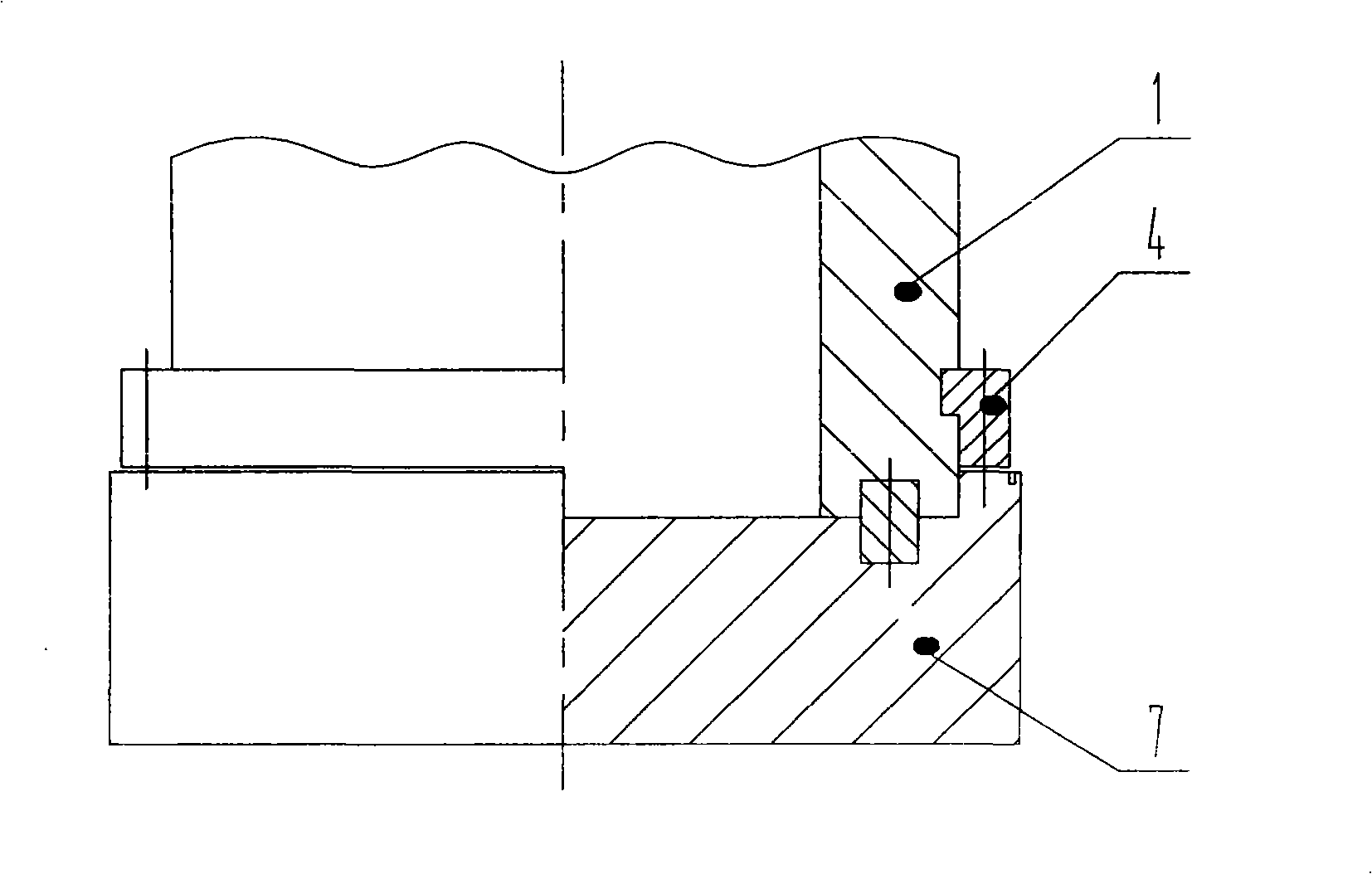
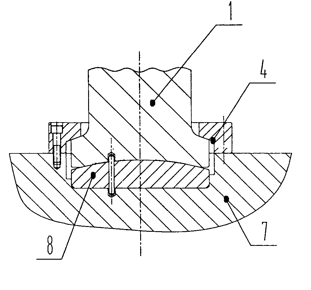
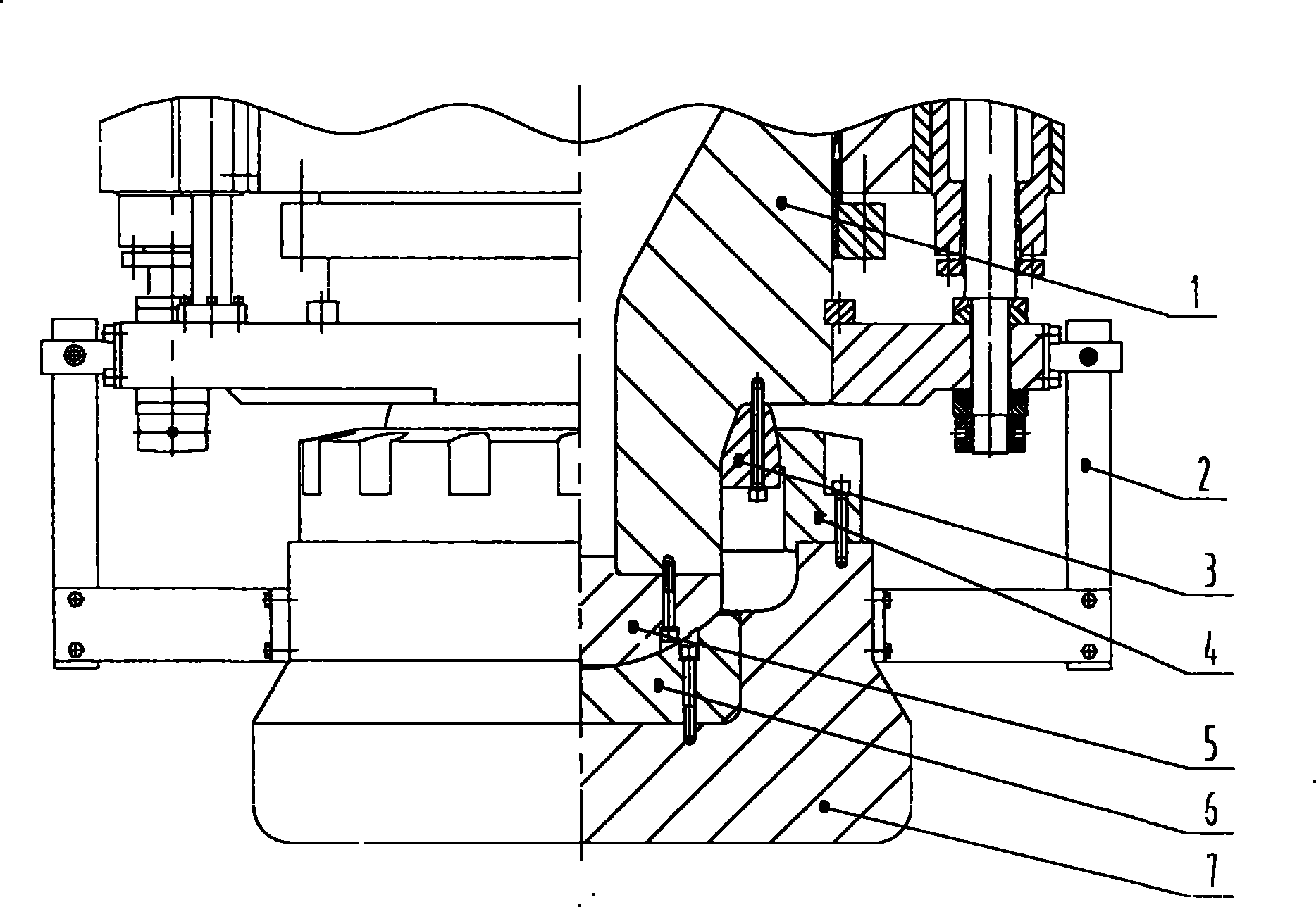
[0016] Such as image 3 As shown, a connection device between the main plunger and the pressure head of a vertical hydraulic machine, the main plunger 1 is in contact with the spherical surface of the upper spherical body 3 and connected by bolts, and the plane of the main plunger 1 and the lower spherical body 5 is connected by bolts , the upper and lower spherical surfaces have the same spherical center, the main plunger 1 forms a discontinuous sphere with the upper and lower spherical surfaces; the indenter 7 and the plane of the spherical support pad 6 are connected by bolts, and the spherical surface of the spherical support pad 6 is in contact with the spherical surface of the lower spherical body 5 , the pressure flange 4 and the pressure head 7 are connected by bolts, the side surface of the pressure flange 4 is in contact with the side surface of the upper spherical body 3, and the pressure head 7 forms a discontinuous inner sphere with the pressure flange 4 and the sp...


PUM


Abstract

The invention discloses a device for connecting a main plunger and a pressure head of a vertical hydraulic machine and relates to a vertical hydraulic machine. The device is characterized in that the main plunger and the spherical surface of an upper sphere body are contacted and connected through a bolt; the main plunger and the plane of a lower sphere body are connected through the bolt; the upper sphere body and the lower sphere body have the same sphere center; the pressure head and the plane of a sphere supporting pad are connected through the bolt; the spherical surface of the sphere supporting pad is contacted with the spherical surface of the lower sphere body; a pressure flange and the pressure head are connected through the bolt; and the side curved surface of the pressure flange is contacted with the side curved surface of the upper sphere body. The device solves the problems that in a structure of directly connecting the main plunger and the pressure head through the pressure flange, a copper sleeve of a main cylinder has serious uneven wear of the seal caused by uneven loading of a presser and in a structure of adopting single spherical surface contact and pressure flange connection between the main plunger and the pressure head, the bolt for connecting the pressure flange and the pressure head is easy to break.

Description

technical field [0001] The present invention relates to vertical hydraulic machines. Background technique [0002] The connection device between the main plunger and the pressure head of the vertical hydraulic press in the prior art mainly has two structures: [0003] 1) The main plunger and the pressure head are directly connected through the pressure flange (such as figure 1 As shown), its disadvantage is that when the surface of the workpiece being pressed has a large curvature, the press will be eccentrically loaded, and its eccentrically loaded force will directly act on the main plunger through the connection key between the indenter and the main plunger. As a result, the main plunger bears a large eccentric load, and the copper sleeve and seal of the main cylinder are severely worn. Therefore, the copper sleeve and seal need to be replaced frequently. [0004] 2) The main plunger and the pressure head adopt a single spherical contact and are connected by a pressure ...

Claims


Application Information

Patent Timeline
Patent Type & Authority Patents(China)
IPC IPC(8): B30B15/06
Inventor 杨文一李翔赵国栋葛文中
Owner TAIYUAN HEAVY IND
Why Eureka
Try Eureka