Plug with separating mechanism of unlocking sleeve

A separation mechanism and unlocking sleeve technology, which is applied to the parts, electrical components, coupling devices and other directions of the connecting device, can solve the problem of inability to unlock and separate the rod head seat, achieve convenient maintenance, simplify the projectile structure, and narrow the operating space. Effect

Active Publication Date: 2010-12-08
杭州航天电子技术有限公司
View PDF0 Cites 0 Cited by
  • Summary
  • Abstract
  • Description
  • Claims
  • Application Information

AI Technical Summary

Problems solved by technology

[0002] Most of the separation and separation electrical connectors at home and abroad use a pull wire separation mechanism, such as J599 / 29 and J599 / 30 pull wire separation electrical connectors of the MIL-DTL-38999 series. The separation mechanism is generally installed on the free end connector (plug). That is to say, the separation of the head seat can only be realized by pulling the separation cable on the free end connector. There is no separation mechanism on the fixed end connector (socket), and the separation of the head seat cannot be directly realized through the fixed end connector.
[0003] The central pull rod mechanism commonly used in domestic separation and fall-off electrical connectors is also mostly installed on the free end connector (plug), which can be separated by pulling the pull rod. There is no separation mechanism on the fixed end connector (socket), and it cannot be connected through the fixed end. The device directly realizes the separation of the head seat
And when the user needs to install the separation mechanism on the fixed-end connector, the pull-rod separation or electromagnetic separation from the plug and socket can also be realized through the central pull-rod mechanism, but when the fixed-end connector is installed on the missile, the connection mechanism must be Inside the missile, the head seat can be unlocked through the internal mechanism when the missile is launched, but due to the lack of manual operation space during normal testing, the head seat cannot be unlocked and separated directly through the pull rod

Method used


Image

  • Plug with separating mechanism of unlocking sleeve
  • Plug with separating mechanism of unlocking sleeve
  • Plug with separating mechanism of unlocking sleeve

Examples


Embodiment Construction

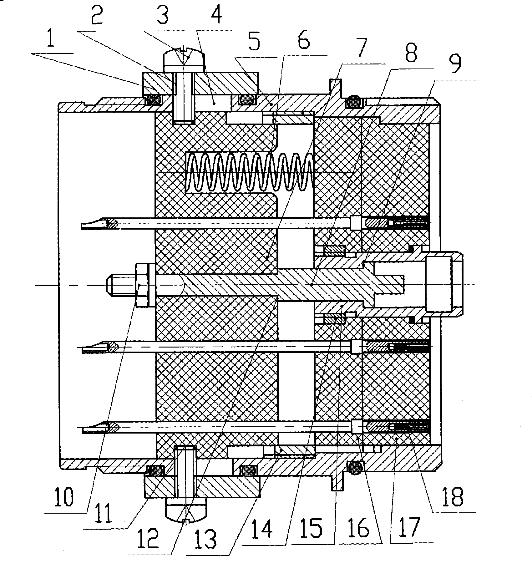
[0011] Such as figure 1 As shown, the unlocking sleeve separation mechanism is provided with an unlocking sleeve 1, and the unlocking sleeve is provided with 4 threaded holes 2, and the threaded holes 2 cooperate with 4 screws 3. There is a waist-shaped groove 4 on the shell 5, and the screw can move in the waist-shaped groove 4. After the screw is installed in place, the unlocking sleeve can be restricted on the housing and will not come out of the connector.

[0012] After the screw 3 is installed, it passes through the four waist-shaped grooves 4 on the housing 5 and enters the four counterbores 11 provided on the movable insulating plate 7 . After the screw 3 is installed in place, it can move with the unlocking sleeve 1 in the groove 4 on the housing 5, and drive the movable insulating plate 7 to move together. There is a through hole in the center of the movable insulating plate 7, and the ejector rod 8 passes through the through hole, and is fixed on the movable insul...


PUM


Abstract

A plug with a separating mechanism of an unlocking sleeve mainly comprises an unlocking sleeve, a casing, a movable insulating board, an ejector rod, an insulation board, a panel, a locking sleeve, and a spring, wherein, the unlocking sleeve and the movable insulating board are respectively arranged outside and inside the casing, the unlocking sleeve passes through a groove formed on the casing through a bolt installed on the unlocking sleeve and enters a counter bore of the movable insulation board, the bolt can move in the groove formed on the casing along with the unlocking sleeve, the ejector rod passes through a central through hole of the movable insulating board and is fixed on the movable insulating board, the front end of the ejector rod is clamped in the locking sleeve, the locking sleeve is fixed on the central through hole of the insulation board and the panels, the insulating board and the panel are fixed on the casing, an insertion hole is formed between the insulating board and the panel, and the spring is arranged between the movable insulating board and the insulating board so as to avoid the accidental movement of the unlocking sleeve.

Description

technical field [0001] The invention belongs to the field of detachable electrical connectors, and relates to a plug with an unlocking sleeve separation mechanism. Background technique [0002] Most of the separation and separation electrical connectors at home and abroad use pull wire separation mechanisms, such as J599 / 29 and J599 / 30 pull wire separation electrical connectors of the MIL-DTL-38999 series. The separation mechanism is generally installed on the free end connector (plug). That is to say, the separation of the headstock can only be realized by pulling the separation cable on the free-end connector, and the fixed-end connector (socket) is not provided with a separation mechanism, so the separation of the headstock cannot be directly realized by the fixed-end connector. [0003] The central pull rod mechanism commonly used in domestic separation and fall-off electrical connectors is also mostly installed on the free end connector (plug), which can be separated by...

Claims


Application Information

Patent Timeline
Patent Type & Authority Patents(China)
IPC IPC(8): H01R13/633H01R13/639
Inventor 张利彬朱海荣章凯冯国华周奇
Owner 杭州航天电子技术有限公司
Why Eureka
Try Eureka