Angle adjustable cradling piece connection device

A connection device and angle adjustment technology, which is applied in tents/canopies, building types, buildings, etc., can solve the problems of inability to change the shape, build different shapes, reduce the effect of equipment, etc., and achieve the effect of a large angle adjustment range

Inactive Publication Date: 2009-06-03
AIR FORCE UNIV PLA
View PDF0 Cites 4 Cited by
  • Summary
  • Abstract
  • Description
  • Claims
  • Application Information

AI Technical Summary

Problems solved by technology

[0002] With the development of the economy and the improvement of living standards, people's pursuit of quality of life is getting higher and higher. In order to meet people's needs for sunshade, rain protection, and building model buildings, many related products such as awnings have appeared in daily life. , tents, etc., but these products generally only have regular shapes or outlines, and cannot change the shape according to different user needs while completing the required functions
Model ceilings of various shapes can often be seen in cultural squares, parks and other places in many cities, but they are often preformed or constructed by a combination of a large number of rigid rods, and cannot quickly change their outlines according to different seasons and occasions to build different shapes
In addition, in terms of camouflage protection for military equipment, the existing support devices cannot adjust the camouflage shape according to changes in the surrounding landforms, thus greatly reducing the effectiveness of the equipment.

Method used


Image

  • Angle adjustable cradling piece connection device
  • Angle adjustable cradling piece connection device
  • Angle adjustable cradling piece connection device

Examples


Embodiment Construction

[0027] The structure of the present invention will be further described in detail below in conjunction with the description of the drawings and specific embodiments.

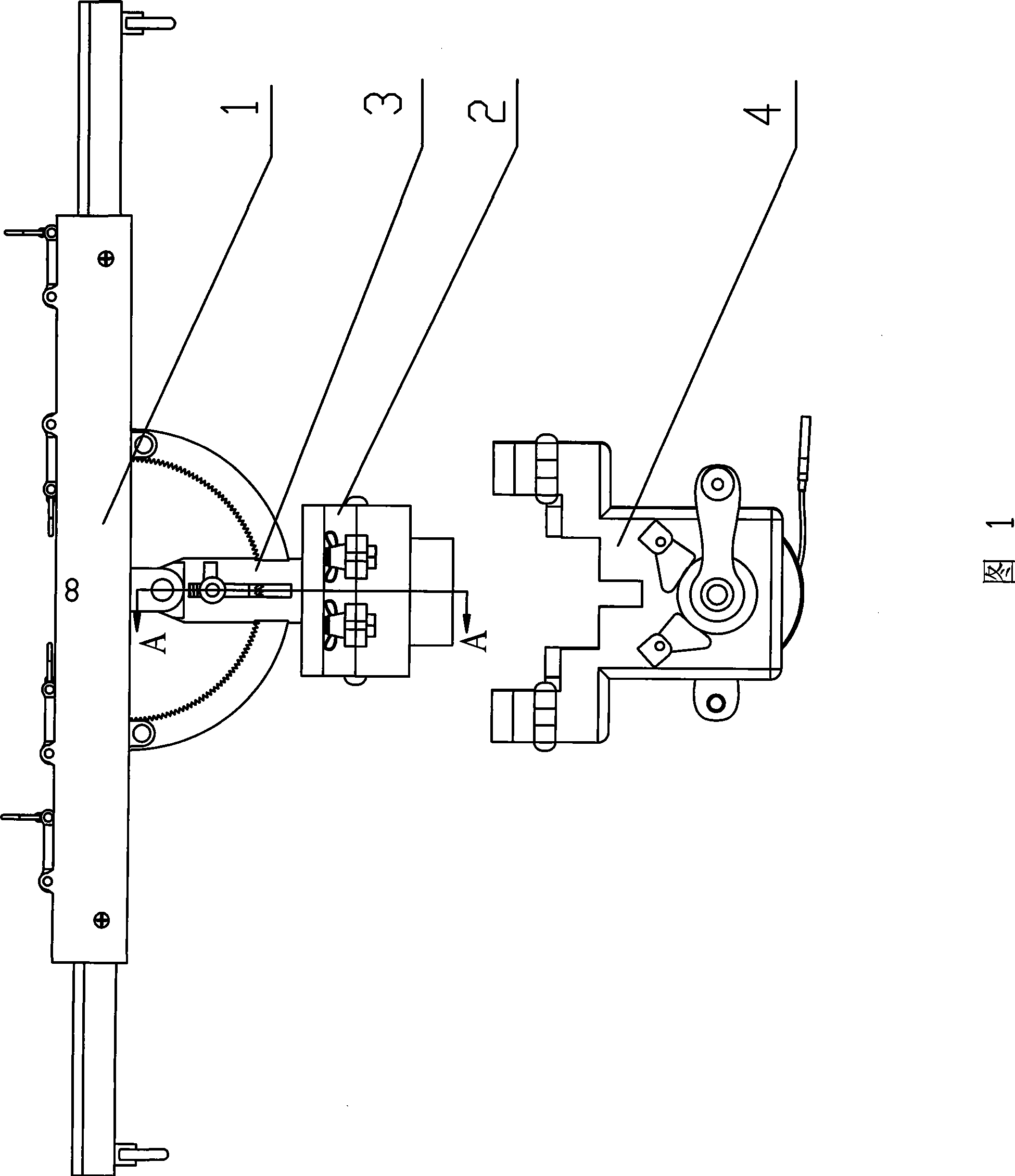
[0028] Referring to Figure 1 and Figure 2, it is specifically a bracket rod connection device with angle adjustment, which mainly includes: clamp 1 for fastening the flexible rod, locking seat 2 for fastening the bracket rod, connecting clamp 1 and locking seat 2, an angle-adjustable locking mechanism 3 and an adjustment mechanism 4 for adjusting the angle.

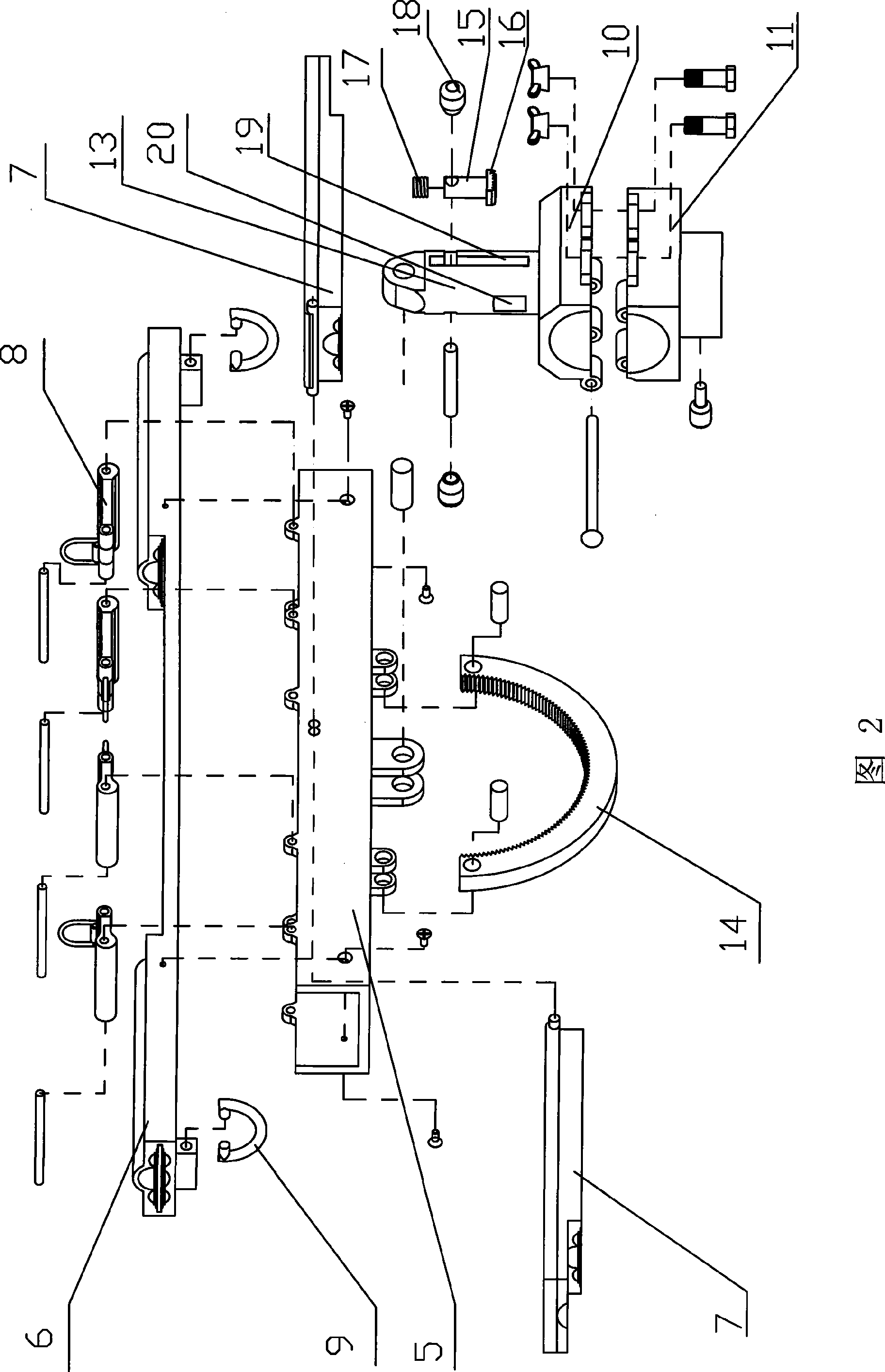
[0029] (1) The clamp 1 for fastening the flexible rod mainly includes: a groove-shaped deck 5 with an upward opening, a multi-section hole combined force arm bar 6 arranged in the slot of the deck 5, two hinged joints on the wall of the slot of the deck 5 A pressing plate 7, four cam pressing mechanisms 8 hinged on the top of the deck 5 groove walls, each pressing plate 7 corresponds to two cam pressing mechanisms 8.

[0030] The multi-section hole combine...


PUM


Abstract

The invention discloses an angle adjustable cradling piece connection device, which comprises a clamp (1), a locking seat (2) and a locking mechanism (3), wherein, the locking mechanism (3) comprises an inner-toothed arc (14), a spring (17), a positioning rod (15), an outer-toothed arc (16) which is fixed at the lower end of the positioning rod (15), and a derrick boom (13) which is arranged on the locking seat (2); a first key slot (19) and a second key slot (20) which are perpendicular to each other are formed longitudinally on the derrick boom (13); blind holes are formed at the bottom end of the derrick boom (13); the spring (17), the positioning rod (15) and the outer-toothed arc (16) are arranged in the blind holes; the inner-toothed arc (14) which is meshed with the outer-toothed arc (16) penetrates the second key slot (20) in a sliding manner; two positioning operating handles (18) which are extended from the first key slot (19) respectively are arranged on the positioning rod (15); and the bottom part of the clamp which are fixed with the two ends of the inner-toothed arc (14) is hinged with the top end of the derrick boom (13).

Description

technical field [0001] The invention relates to a support rod connection device, in particular to a support rod connection device with angle adjustment, which is suitable for the field of support rod connection and angle adjustment with a flexible shaped ceiling. Background technique [0002] With the development of the economy and the improvement of living standards, people's pursuit of quality of life is getting higher and higher. In order to meet people's needs for sunshade, rain protection, and building model buildings, many related products such as awnings have appeared in daily life. , tents, etc., but these products generally only have regular shapes or outlines, and cannot change the shape according to different user needs while completing the required functions. Model ceilings of various shapes can often be seen in cultural squares, parks and other places in many cities, but they are often preformed or constructed by a combination of a large number of rigid rods, an...

Claims


Application Information

Patent Timeline
Patent Type & Authority Applications(China)
IPC IPC(8): E04H15/34
Inventor 王崴韩华亭杨云李培林范海雄赵敏荣徐晓东
Owner AIR FORCE UNIV PLA
Why Eureka
Try Eureka