Linkage rod type air chuck for laser pipe cutter

A technology of pneumatic chuck and pipe cutting machine, which is applied in the direction of laser welding equipment, welding/cutting auxiliary equipment, auxiliary devices, etc. It can solve the problems of inaccurate centering, less suitable pipe diameter, and large influence of pipe diameter tolerance. Realize the effect of automatic control of loose clamp and adjustable clamping force

Inactive Publication Date: 2009-05-27
CHANGCHUN BEIXING LASER EQUIP
View PDF0 Cites 12 Cited by
  • Summary
  • Abstract
  • Description
  • Claims
  • Application Information

AI Technical Summary

Problems solved by technology

It can be seen from the figure that the structure of the iron-stop pneumatic chuck is relatively simple, and there are many disadvantages. It is greatly affected by the tolerance of the pipe diameter, the centering is not accurate, there is a setting error, and the adaptability to the pipe diameter is small. Multiple processing needs to be constantly replaced to adapt to different clamping blocks. Pipe diameter requirements, etc.

Method used


Image

  • Linkage rod type air chuck for laser pipe cutter
  • Linkage rod type air chuck for laser pipe cutter
  • Linkage rod type air chuck for laser pipe cutter

Examples


Embodiment Construction

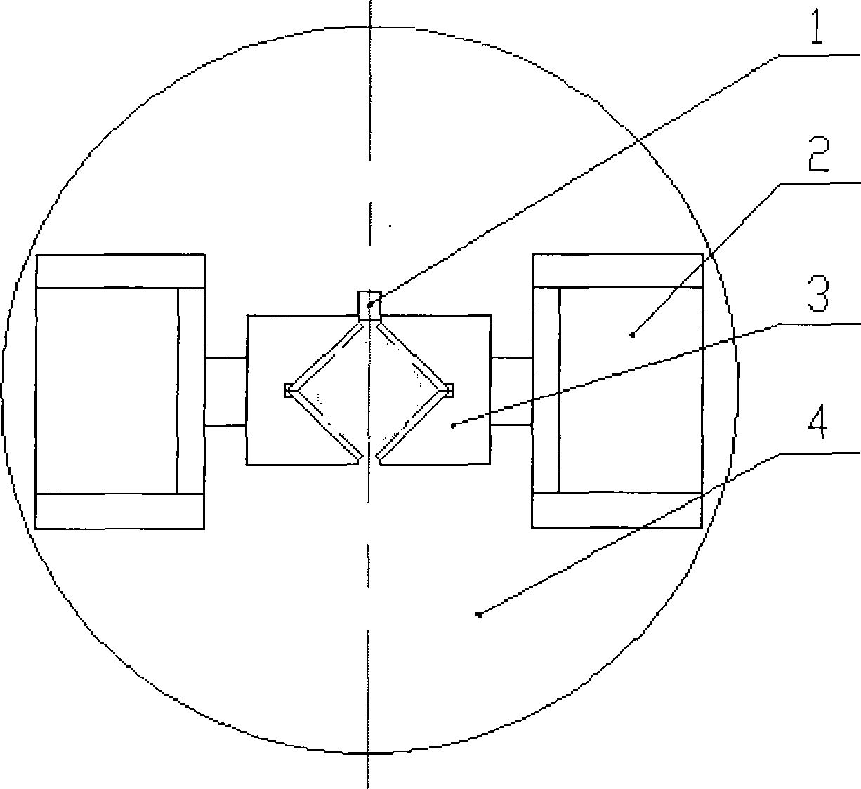
[0010] The invention according to figure 2 , image 3 The structure shown is implemented, wherein the horizontal transverse guide rail 5 and the horizontal longitudinal guide rail 11 are linear rolling guide rails produced by Dalian Hanyi Seiko Enterprise Co., Ltd. (the models are respectively BRH15B2L360HZ1 II and BRH15B2L98HZ1 II), and the spring 14 is adopted from Japan Co., Ltd. Tokyo The mold spring produced by the clockwork factory (model is TM27×050), the disc body seat 13, the weight block 12 adopts Q235, the gasket 17 adopts T10, and the remaining parts are connecting rod 8, cylinder 9, cylinder connecting seat 20, piston 15. Clamp block 16, horizontal vertical slide plate 10, horizontal horizontal slide plate 7, and slide block 6 are all made of 45# steel. The size of the entire chuck is designed according to the diameter of the processed pipe, and the size of each component involved is based on the size of the chuck. The size of the disk is designed.


PUM


Abstract

The invention provides a connecting rod typed gas static-pressing chuck used for a laser pipe cutting machine, belonging to a chuck in the field of mechanical equipment technique. The technical problem to be solved is that the connecting rod typed gas static-pressing chuck used for the laser pipe cutting machine is provided; the technical proposal comprises a horizontal transverse sliding connecting rod mechanism, a horizontal longitudinal clamping mechanism and a chuck seat; the whole chuck takes the longitudinal symmetry axis as a center; the horizontal longitudinal clamping mechanism is symmetrically arranged in longitudinal direction of the chuck; the transverse symmetry axis is taken as a center, the left side of the chuck is provided with the horizontal transverse connecting rod mechanism and the right side thereof is provided with a counterweight. The chuck controls the clamping force by inflating and deflating the cylindrical and by extending and contracting the spring so as to complete a working period of loosening and clamping of the pipes, and is provided with a through hole which allows the pipes to pass by; the clamping block can be adjusted upwards and downwards and the sliding block can be adjusted to the left and the right; the concentricity in a large range can be adjusted without the requirement of replacing the clamping block; the connecting rod typed gas static-pressing chuck is applicable to the clamping requirement of various pipe diameters and can automatically control the loosening and clamping of the chuck.

Description

technical field [0001] The invention belongs to the technical field of mechanical equipment and relates to a novel special chuck for a laser pipe cutting machine. Background technique [0002] Laser pipe cutting machine is a kind of pipe processing equipment, which drives the pipe to rotate through the chuck, and the laser head moves relative to the pipe axis to synthesize the cutting track, and can realize the long pipe processing requirements through segmented serial cutting, in which the pipe rotation index is It is driven by the chuck, so the chuck is one of the most critical components in the laser pipe cutting machine equipment. The laser pipe cutting machine chucks that are usually used before the present invention mainly have the following forms: iron stop type pneumatic chuck, spring type pneumatic chuck, electric chuck and so on. Wherein the prior art closest to the present invention is the self-made iron stop type pneumatic chuck of Changchun Institute of Optics,...

Claims


Application Information

Patent Timeline
IPC IPC(8): B23K37/053B23K26/42B23K26/70
Inventor 李雨田
Owner CHANGCHUN BEIXING LASER EQUIP
Why Eureka
Try Eureka