
Valve mechanism for switch cabinet

A technology of switch cabinets and valves, which is applied in the direction of substation/power distribution device shells, etc., which can solve the problems of valve opening and closing, which are complicated and inflexible, occupy a large space, and affect the installation of switch cabinets, and achieve simple structure, small space occupation, and increased The effect of the degree of protection

Inactive Publication Date: 2010-09-08
TIANJIN JIUAN GRP
View PDF0 Cites 0 Cited by
  • Summary
  • Abstract
  • Description
  • Claims
  • Application Information

AI Technical Summary

Problems solved by technology

This technical solution has the following technical disadvantages: the split valve mechanism adopts connecting rod transmission, the opening and closing of the valve is complicated and inflexible, and takes up a lot of space, which affects the installation of other components of the switch cabinet

Method used


Image

  • Valve mechanism for switch cabinet
  • Valve mechanism for switch cabinet

Examples


Embodiment Construction

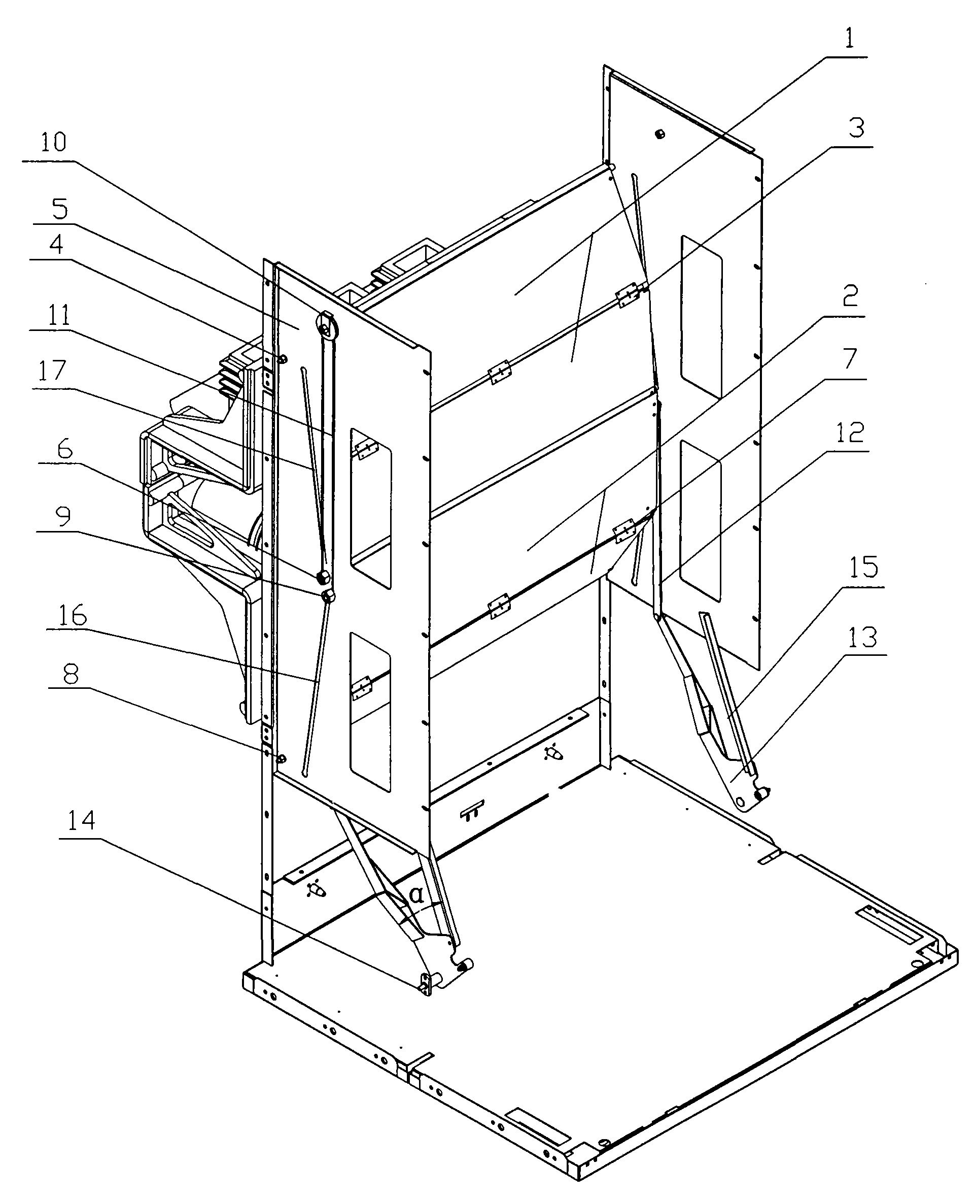
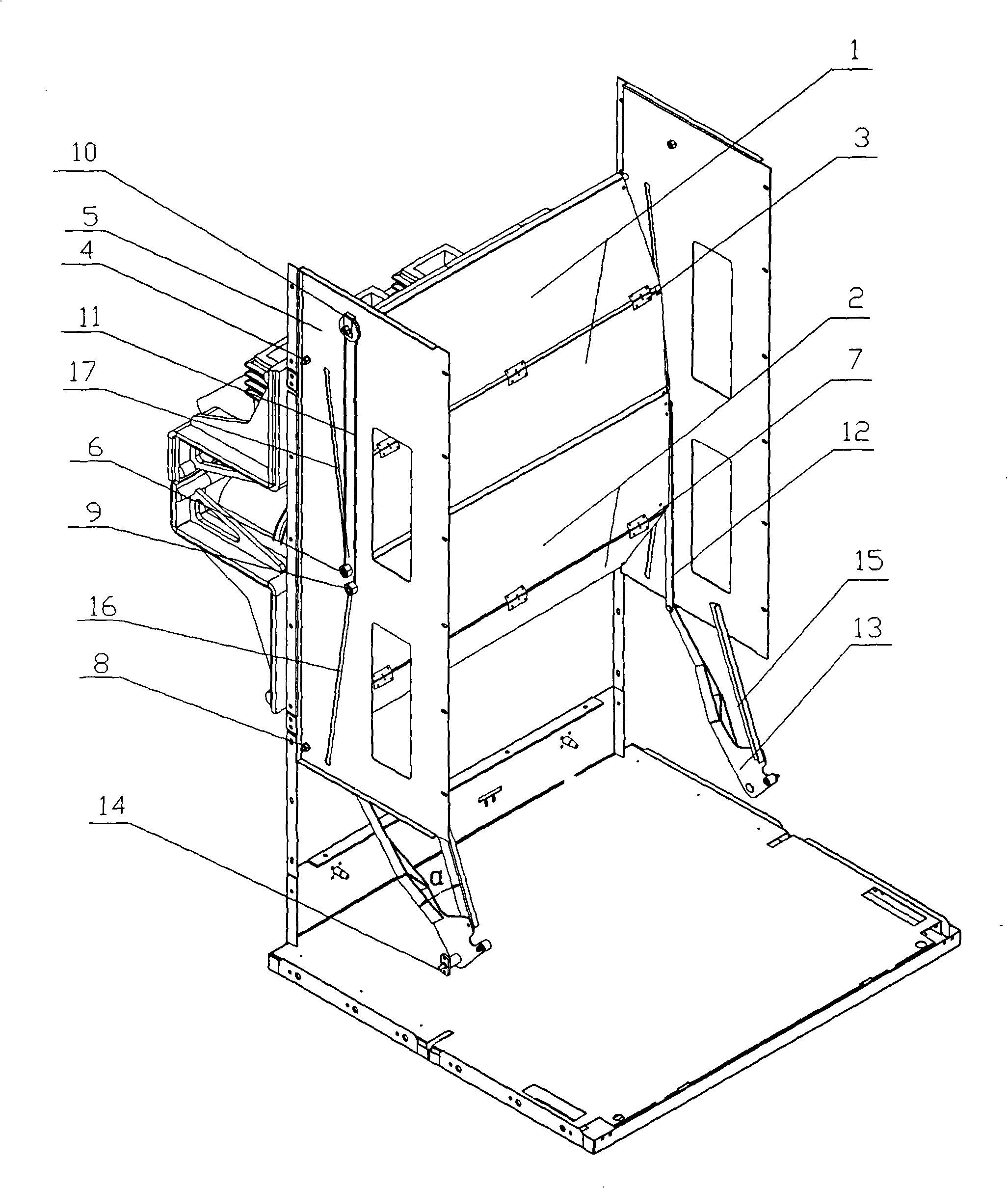
[0013] In order to further understand the invention content, characteristics and effects of the present invention, the following examples are given, and detailed descriptions are as follows in conjunction with the accompanying drawings:

[0014] The valve mechanism of a switch cabinet in the present invention fully combines engineering mechanics and mechanical transmission principles. The automatic closing of the valve is to apply the principle of engineering mechanics to the mechanism properly, so that the valve can be closed without external force. Automatic shutdown, thus better guarantee the safety of the operator.

[0015] The present invention mainly comprises three parts: the valve partition, the connection of the valve partition and the automatic opening and closing of the valve. The valve partition is used to block the high-voltage electrified body and is processed by four steel plates. The connection of the valve partition mainly uses a steel wire to connect the fou...


PUM


Abstract

The invention discloses a movable door mechanism of a switch cabinet. The movable door mechanism comprises a movable door upper clapboard and a movable door lower clapboard which are arranged on a left lateral plate and a right lateral plate in a closed state or an open state; both the upper clapboard and the lower clapboard are connected by two partition plates through hinges; the upper clapboard is in rotatable connection with the left lateral plate and the right lateral plate of the mechanism; two sides of the bottom of the upper clapboard are provided with a sliding roller of the upper clapboard; the sliding roller of the upper clapboard is embedded into an intilted directed slideway correspondingly arranged on the left lateral plate and the right lateral plate of the mechanism; a mounting structure of the upper clapboard and the structure are symmetrical; the upper clapboard is heavier than the lower clapboard; the upper parts of the left lateral plate and the right lateral plateof the mechanism are provided with a fixed pulley respectively; a steel wire is wound on the fixed pulley; one end of the steel wire is fixedly connected with the sliding roller of the upper clapboard; the other end of the steel wire is fixedly connected with the sliding roller of the lower clapboard; a transmission connecting rod is hinged on the sliding roller of the lower clapboard; and the lower end of the transmission connecting rod is hinged with a transmission turning arm. The movable door mechanism has a simple structure and flexible and reliable opening and closing of the movable door.

Description

technical field [0001] The invention relates to a valve mechanism, in particular to a valve mechanism of a switch cabinet. Background technique [0002] The valve mechanism is an important part of the high voltage switchgear. At present, the domestically produced valve mechanism mainly uses a spring mechanism to operate the upper and lower valves; when the removable part is pushed forward to make the movable contact insert into the static contact, the spring linkage mechanism of the valve driven by the movable part hitting the connecting rod will be affected by the external force. Under the action of the valve, the upper and lower valve plates move up and down respectively and open, so that the valves form a synchronous split structure. Otherwise when the removable part is pulled out, under the action of the spring, the connecting rod drives the valve plate to reset it and completely cover the static contact. This technical solution has the following technical disadvantage...

Claims


Application Information

Patent Timeline
Patent Type & Authority Patents(China)
IPC IPC(8): H02B1/26
Inventor 苏伟成
Owner TIANJIN JIUAN GRP
Learn More