
Bidirectional push-pull type hot air isolating door

A hot air isolation door, two-way push-pull technology, applied to door/window accessories, wing leaf arrangement, wing leaf parts, etc., can solve the problems of door panels not being tightly closed, leakage, increased frictional resistance, etc., to reduce maintenance and The failure rate, flexible and reliable opening, and the effect of improving sealing performance

Inactive Publication Date: 2011-11-09
无锡市华东电力设备有限公司
View PDF0 Cites 0 Cited by
  • Summary
  • Abstract
  • Description
  • Claims
  • Application Information

AI Technical Summary

Problems solved by technology

And when the flue gas flow increases, the flue will also be widened and enlarged, and the corresponding thermal insulation door panel will also be enlarged, so the gravity of the door panel itself will also increase, which will increase the frictional resistance and cause the door panel to run It is not flexible; at the same time, the stress and deformation of the door panel are also increased, so that the door panel is not closed tightly, resulting in leakage, and cannot play a role of complete sealing
In actual production, due to errors in production, the door seat and door panel cannot be completely flat, so that the packing on the sealing surface of the door panel and the door seat, the locking eccentric wheel and the door panel cannot be completely contacted. It cannot be completely locked, which also causes leakage and cannot play a role in complete sealing.

Method used


Image

  • Bidirectional push-pull type hot air isolating door
  • Bidirectional push-pull type hot air isolating door
  • Bidirectional push-pull type hot air isolating door

Examples


Embodiment Construction

[0014] Below the present invention will be further described in conjunction with the embodiment in the accompanying drawing:

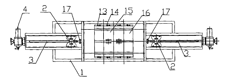
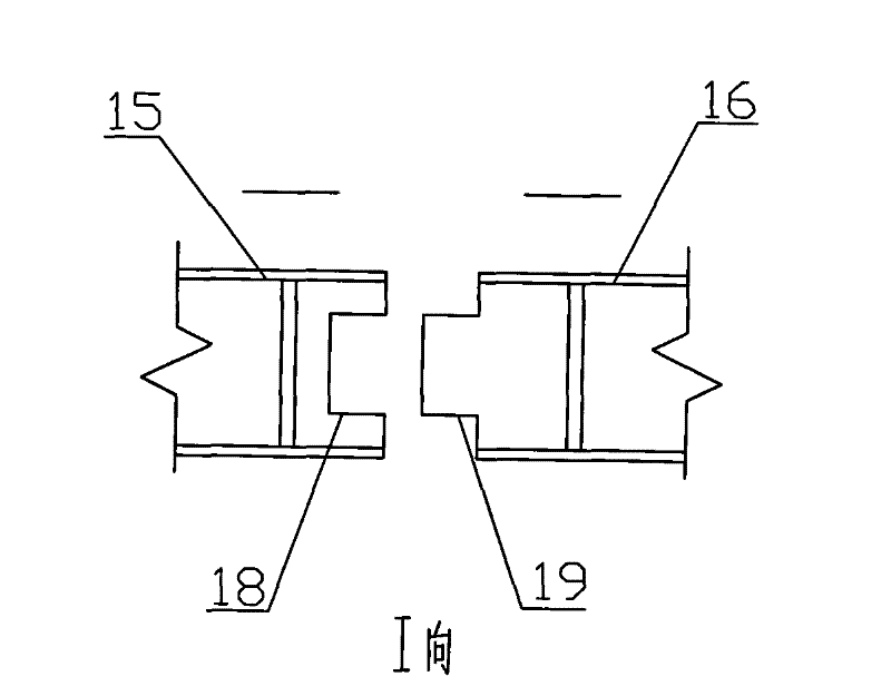
[0015] Such as Figure 1 to Figure 4 As shown, it includes door frame 1, transmission nut body 2, transmission screw 3, electric actuator 4 (pneumatic actuator is also acceptable), inspection hole cover 5, push-pull rod support 6, guide rail 7, door panel sealing surface 8, hard Sealing device 9, push-pull rod 10, door panel away from the sealing surface side 11, push-pull rod seat 12, load-bearing wheel 13, guide wheel 14, first door panel 15, second door panel 16, push-pull rod disc change box 17 concave surface 18, convex Shape surface 19, flat sheet 20, corner sheet 21, pressing plate 22 and sealing side plate 23 etc.

[0016] In the present invention, the first door panel 15 and the second door panel 16 are movable parts of the isolation door, and are placed in the door frame 1 . A set of driving devices are respectively installed symmetrically ...


PUM


Abstract

The invention relates to a bidirectional push-pull type hot air isolating door which is characterized in that the two sides of a door frame are provided with driving devices in a symmetrical way; each driving device comprises a driving nut body, a drive screw, an electric executing device, a push-pull rod support seat, a push-pull rod and a push-pull rod seat, wherein one end of the drive screw is connected on the door frame, and the other end thereof is meshed and connected with the electric executing device; the driving nut body is fixed under the push-pull rod support seat; one end of the push-pull rod is installed on the push-pull rod support seat, and the other end thereof is arranged on the push-pull rod seat; and the push-pull rod seat is arranged at the side where a door sheet deviates from a sealing surface, and the push-pull rod is connected with the door sheet by the push-pull rod seat. The hot air isolating door is provided with the door sheet which is divided into two parts that can move towards the two sides, are respectively controlled by a set of executing mechanism and have no mutual interference; the door sheet can be flexibly and reliably opened, has high strength and does not cause stress deformation; the door sheet can be put away into the door, so that dust can not be leaked on the door sheet in a room; furthermore, the hot air isolating door can continuously blow and sweep the sealing surface, thus reducing the maintenance and the failure rate and greatly improving the sealing performance of the hot air isolating door.

Description

technical field [0001] The invention relates to a two-way push-pull hot air isolation door, specifically, it is suitable for boiler systems of large units of thermal power plants such as 600MW and 1000MW ultra-wide and super-large flue ducts. . Background technique [0002] In the prior art, the two-way push-pull hot air isolation door installed in the vertical flue mainly includes a door seat, a door panel, an electric / pneumatic actuator, and the like. Usually, two door panels are opened to both sides, so there must be enough space on both sides of the flue, and the electric / pneumatic actuator needs to be installed parallel to the ground. [0003] The original design of the hot air isolation door is mostly used in the flue with a small smoke flow, so the door panel is a whole. And when the flue gas flow increases, the flue will also be widened and enlarged, and the corresponding thermal insulation door panel will also be enlarged, so the gravity of the door panel itself w...

Claims


Application Information

Patent Timeline
Patent Type & Authority Patents(China)
IPC IPC(8): E06B3/46E06B5/10E06B7/16E05D13/00
Inventor 马凌芸
Owner 无锡市华东电力设备有限公司
Learn More