
Centrifugal pump body

A centrifugal pump and pump body technology, which is applied in the field of monitoring the running stability of centrifugal pumps, can solve the problems of reducing the structural strength of the position of the separator, affecting the normal operation of the entire pump, etc., and achieves the effect of prolonging the service life.

Inactive Publication Date: 2009-05-20
CHINA AGRI UNIV
View PDF0 Cites 6 Cited by
  • Summary
  • Abstract
  • Description
  • Claims
  • Application Information

AI Technical Summary

Problems solved by technology

Since the thickness of the diaphragm of the centrifugal pump is relatively thin, if the pressure hole is directly opened at the position of the diaphragm, the structural strength of the diaphragm may be reduced, and even the normal operation of the whole pump will be affected.

Method used


Image

  • Centrifugal pump body
  • Centrifugal pump body
  • Centrifugal pump body

Examples


Embodiment Construction

[0019] The following examples are used to illustrate the present invention, but are not intended to limit the scope of the present invention.

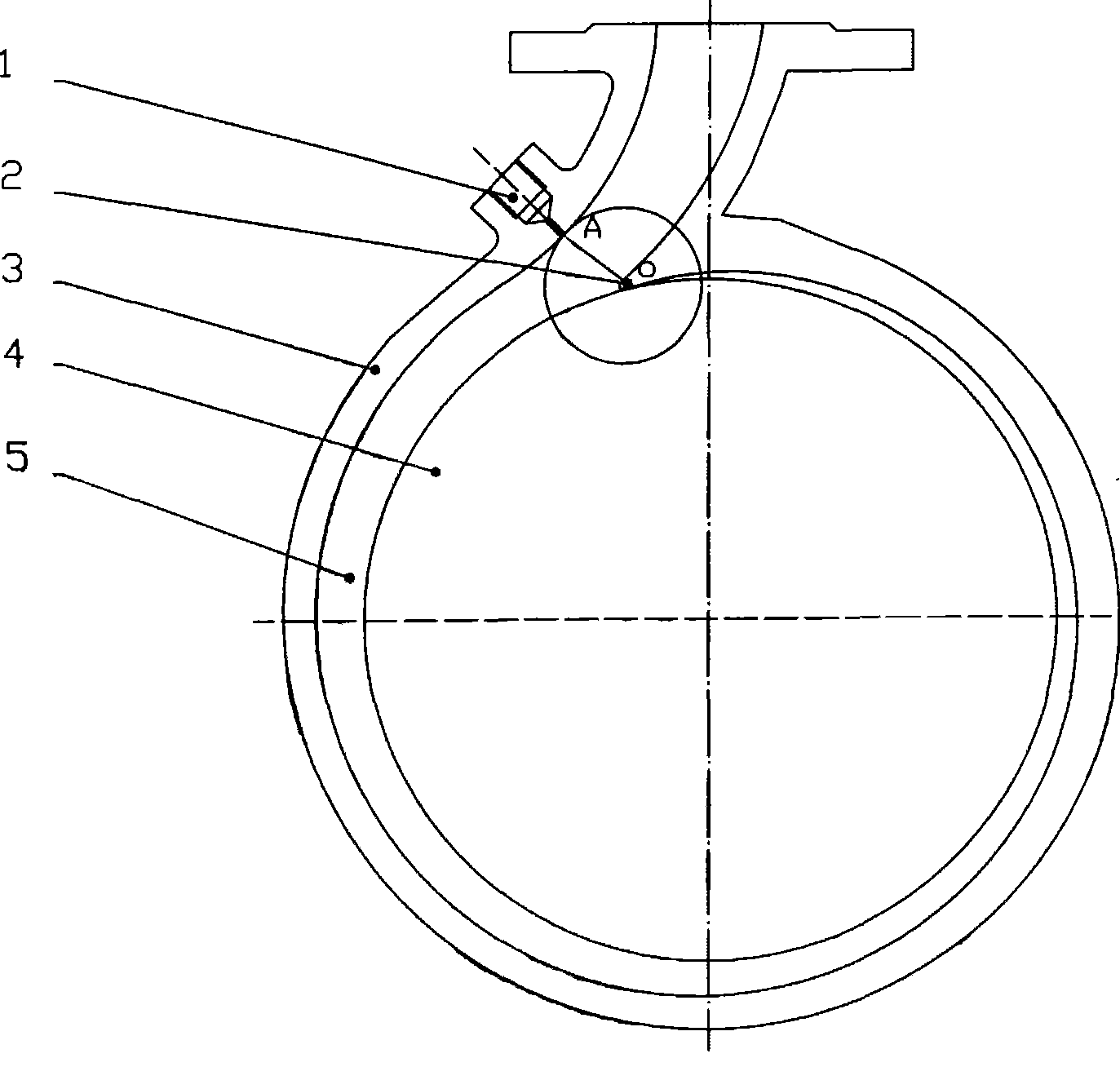
[0020] Such as figure 1 As shown, the pressure-taking hole 1 is set on the pump body 3 of the centrifugal pump. On the center section of the pump body of the centrifugal pump, an auxiliary circle is drawn with the point O on the end of the tongue 2 as the center of the circle, so that the auxiliary circle is in line with the inner wall of the pump body 3. Cut, the tangent point is recorded as point A, the present invention uses point A as the pressure taking point of the pressure taking hole 1 on the inner wall of the pump, and simultaneously uses the extension of the line segment OA as the center line of the pressure taking hole 1.

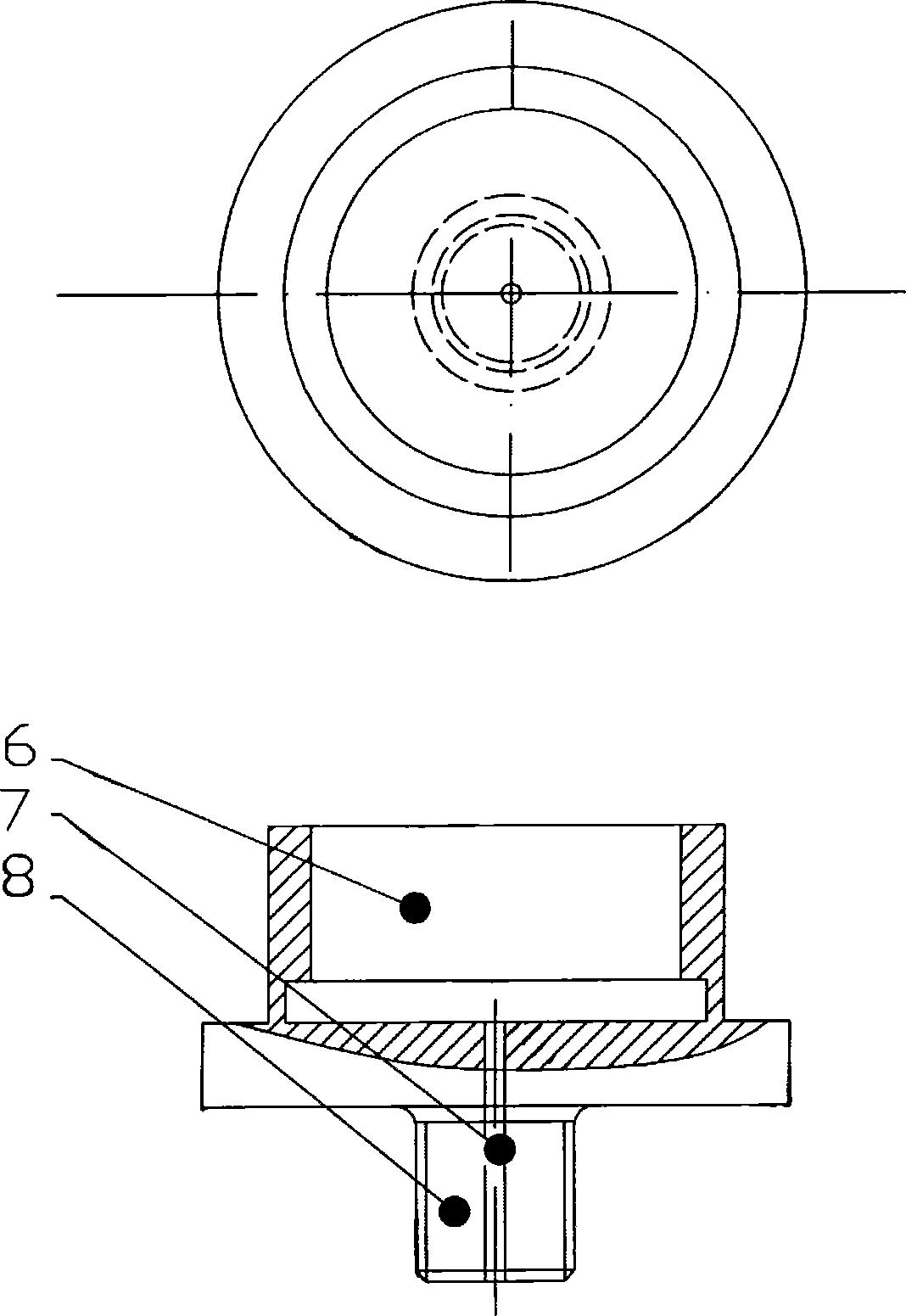
[0021] The pressure-taking hole 1 is designed as two ends. Looking from the outer wall of the pump body 3 to the inner wall, the diameter of the first section of the hole is G3 / 8, and the length is 15mm....


PUM

PropertyMeasurementUnit
Lengthaaaaaaaaaa
Diameteraaaaaaaaaa

Abstract

The invention relates to a pump body of a centrifugal pump, which comprises a pressure tapping hole on the pump body and a baffle tongue inside the pump body; the position of the pressure tapping hole is designed in a mode that an auxiliary circle in the central section of the pump body taking the tongue tip of the baffle tongue as a center of the circle is tangential with the inner wall of the pump body; and the extension line of the connecting line between the tongue tip and the tangent point is used as the centerline of the pressure tapping hole. The pump body has the advantages that: firstly, the pump body can judge the working condition of the operation of the centrifugal pump through monitoring pressure pulsation amplitude value; and under the same working condition, the change of the pressure pulsation amplitude value also reflects the change of the position of a blade relative to the baffle tongue; and secondly, the condition of pressure pulsation in a baffle tongue region reflects the stability of the operation of the centrifugal pump in corresponding degree; therefore, the pump body can effectively avoid the operation of the centrifugal pump under the working condition of large pressure pulsation and prolong the service life of the centrifugal pump.

Description

technical field [0001] The invention relates to the field of monitoring the running stability of a centrifugal pump, in particular to monitoring the pressure pulsation generated in the diaphragm area of ​​the centrifugal pump. Background technique [0002] At present, centrifugal pumps are widely used in various sectors of the national economy and cutting-edge technical fields such as aerospace as an important energy conversion and fluid transportation energy supply device. Therefore, improving the safety and reliability of operation and reducing vibration and noise not only has huge economic benefits, but also has great significance for improving the development level of my country's pump industry. [0003] With the improvement of the requirements for the operational reliability of centrifugal pumps, it is necessary to monitor the operating status of centrifugal pumps and make correct judgments based on the monitoring results. The experimental research on the internal flow...

Claims


Application Information

Patent Timeline
IPC IPC(8): F04D29/42F04D29/66F04D17/00
Inventor 王福军姚志峰肖若富夏伟
Owner CHINA AGRI UNIV
Learn More