
Gap-adjusting structure of high-accuracy numerical control drill

A high-precision, gap-adjusting technology, applied in metal processing and other directions, can solve the problems of difficult matching accuracy, low drilling accuracy level, and inability to adjust, etc., to achieve the effects of convenient production, improved accuracy level, and reasonable structure.

Inactive Publication Date: 2009-05-13
WUXI HUALIAN SCI & TECH GROUP
View PDF0 Cites 4 Cited by
  • Summary
  • Abstract
  • Description
  • Claims
  • Application Information

AI Technical Summary

Problems solved by technology

[0002] In the existing technology, the positioning guide of the CNC drilling shaft is completely processed by gold to ensure the gap between the shaft and the shaft sleeve, which cannot be adjusted. grade down

Method used


Image

  • Gap-adjusting structure of high-accuracy numerical control drill
  • Gap-adjusting structure of high-accuracy numerical control drill

Examples


Embodiment Construction

[0009] Below the present invention will be further described in conjunction with the embodiment in the accompanying drawing:

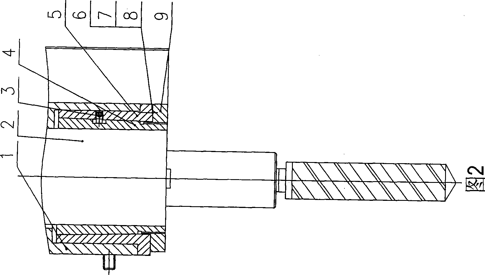
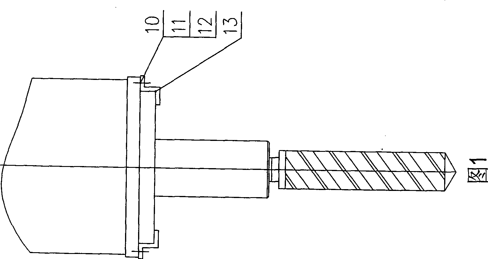
[0010] As shown in Figures 1 to 2, it includes a main shaft seat 1, a main shaft assembly 2, a screw 3, a clearance adjustment sleeve 4, a taper sleeve 5, a bolt 6, a flat washer 7, a spring washer 8, a clearance adjustment nut 9, a bolt 10, a flat Pad 11, spring pad 12, pressing plate 13.

[0011] In the present invention, firstly, the gap adjusting sleeve 4 is installed in the hole 5 of the taper sleeve, screwed on the screw 3, screwed into the groove of the gap adjusting sleeve 4 to form an assembly, the above assembly is installed in the hole of the main shaft sleeve 1, and bolts 6, flat Fix it with pad 7 and spring pad 8, put the main shaft assembly 2 into the hole of the main shaft seat 1 and the gap adjustment sleeve 4, turn the gap adjustment nut 9 to adjust the gap, and use the bolt 10, flat washer 11, spring Pad 12 fixes the position of back...


PUM


Abstract

The invention relates to a clearance adjusting structure of a main shaft of a high-precision numerical control drill, in particular to a main shaft structure suitable for numerical control drilling machine, which belongs to the technical field of machine devices. The clearance adjusting structure is characterized in that the clearance adjusting sleeve is mounted in a conical trepan boring, a screw is screwed on and screwed into a clearance adjusting grooving to form a combined unit, the combined unit is mounted in the trepan boring of the main shaft and fixed through a screw bolt, a flat gasket and a spring washer, the main shaft component is mounted into the main shaft seat and the clearance adjusting trepan boring, a clearance adjusting nut is screwed to adjust the clearance, and a pressure plate is used for fixing the position of the clearance adjusting nut through the screw bolt, the flat gasket and the spring washer. The invention has the advantages that the structure is reasonable, the fabrication is convenient, the manufacturability is strong and the positioning accuracy is high; in the practical drilling hole of the numerical control drill, the radial run-out of the main shaft is small, the drilling is stable and the drilling precision is high; therefore, the accuracy class of the numerical control drilling machine can be enhanced, and the application range of the numerical control drilling machine can be widened.

Description

technical field [0001] The invention relates to a gap adjustment structure of a high-precision CNC drilling spindle, in particular to a spindle structure suitable for a CNC drilling machine, and belongs to the technical field of mechanical equipment. Background technique [0002] In the existing technology, the positioning guide of the CNC drilling shaft is completely processed by gold to ensure the gap between the shaft and the shaft sleeve, which cannot be adjusted. Grade down. Contents of the invention [0003] The purpose of the present invention is to overcome the above disadvantages, thereby providing a high-precision CNC drilling spindle clearance adjustment structure, which can ensure the best sliding fit between the spindle and the spindle sleeve, high positioning accuracy, small radial runout of the spindle, and Improve the accuracy level of CNC drilling machines. [0004] According to the technical solution provided by the present invention, the clearance adju...

Claims


Application Information

Patent Timeline
Patent Type & Authority Applications(China)
IPC IPC(8): B23B19/02B23Q5/56
Inventor 邵燕瑛薛静清陆松茂
Owner WUXI HUALIAN SCI & TECH GROUP
Learn More