On site precision detecting test line for high-voltage current transformer

A high-voltage current and test circuit technology, which is applied in the direction of instruments, measuring devices, and measuring electrical variables, can solve problems such as the cost of voltage regulators, the difficulty of manufacturing technology, the difficulty of ensuring compensation capabilities of capacitors, and the reduction of compensation capabilities. To achieve the effect of reducing the capacity of the test power supply, reducing the number, and reducing the rated voltage

Active Publication Date: 2011-09-14
NORTHWEST CHINA GRID
View PDF0 Cites 0 Cited by
  • Summary
  • Abstract
  • Description
  • Claims
  • Application Information

AI Technical Summary

Problems solved by technology

The parallel compensation capacitor is connected to the primary side of the voltage regulator, and its capacitive reactance compensates the main circuit after changing the ratio of the voltage regulator. Since the voltage regulator is actually a step-down transformer, its ratio is less than 1, so the capacitive reactance changes to two After the secondary side, the actual compensation capability decreases; on the other hand, since the compensation capacitor is connected to the primary side of the voltage regulator, the reactive current of the compensation capacitor still needs to pass through the voltage regulator, so that the voltage regulator needs to provide active power for the main circuit. The (resistive) component needs to pass reactive power compensation current, so the capacity required for the voltage regulator is very large, which is quite unfavorable for the cost of configuring the voltage regulator and the difficulty of manufacturing technology.
[0007] In addition, using the above-mentioned existing technology, it is also reflected from the field measurement process that because the secondary load of the voltage regulator is very large, the primary voltage may have a large drop during the test process. During the field test, the primary side voltage of the voltage regulator was about 400V at the beginning. When the current flow reached about 2000A, the primary side voltage had dropped to about 310V. It was difficult for the capacitor to guarantee its compensation capability, resulting in the failure of the final test.

Method used


Image

  • On site precision detecting test line for high-voltage current transformer
  • On site precision detecting test line for high-voltage current transformer
  • On site precision detecting test line for high-voltage current transformer

Examples


Embodiment Construction

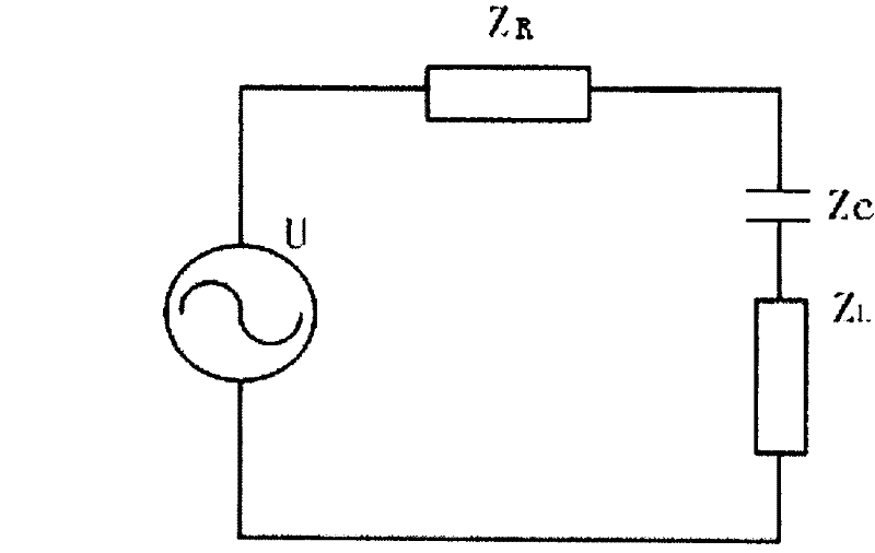
[0019] refer to figure 1 , the high-voltage current transformer on-site accuracy detection test circuit includes voltage regulator T1, current booster T2, compensation capacitor C, test power supply AC electrically connected to the primary side of voltage regulator T1, inductance L and resistance R of the main circuit , the compensation capacitor C is connected in series in the main circuit for series compensation; the voltage of the test power supply AC is reduced after passing through the voltage regulator T1, and then electrically connected to the primary side of the current booster T2, and the secondary side of the current booster T2 is connected to the main circuit circuit It is used to generate the large current required for calibration of the standard current transformer and field current transformer set on the main circuit. Adjusting the voltage on the secondary side of the voltage regulator T1 can adjust the size of the current flowing into the main circuit, and the p...


PUM


Abstract

The invention relates to a high-voltage power transmission and transformation current detecting technology which discloses an on-site accuracy detecting and testing line of a high-voltage current mutual inductor and is adapted to the on-site accuracy detection of an ultra-high voltage (750 kV) current mutual inductor. The on-site accuracy detecting and testing line of the high-voltage current mutual inductor comprises a voltage regulator, a current raising device, a compensated capacitor, a main loop, a testing power supply which is electrically connected with the first side of the voltage regulator, a standard current mutual inductor, an on-site current mutual inductor and a mutual inductor check meter, wherein the standard current mutual inductor and the on-site current mutual inductor are arranged on the main loop, the mutual inductor check meter is electrically connected with the standard current mutual inductor and the on-site current mutual inductor, the second side of the voltage regulator is electrically connected with the first side of the current raising device, and the second side of the current raising device is electrically connected with the main loop. The invention is characterized in that the compensated capacitor is connected in the main loop in series.

Description

technical field [0001] The invention relates to a current detection technology for high-voltage power transmission and transformation, in particular to a test circuit for on-site accuracy detection of a high-voltage current transformer, which is suitable for on-site accuracy detection of an ultra-high voltage (750kV) current transformer. Background technique [0002] The current transformer is the main component of the electric energy metering device in the substation, and its accuracy is very important for the electricity metering. In the previous on-site inspection of transformers in the power system, it was found that some gateway meters had large deviations. For example, in 2000, the comprehensive error of 500kV outgoing line measurement in a power plant exceeded 5%, and the on-site inspection of a 330kV substation found that all capacitive voltage transformers exceeded Poor, these problems will have a great impact on system measurement. For the power transmission and t...

Claims


Application Information

Patent Timeline
Patent Type & Authority Patents(China)
IPC IPC(8): G01R35/02
Inventor 孙强吴经锋黄宗君毛琛琳丁彬李润秋刘毅
Owner NORTHWEST CHINA GRID
Why Eureka
Try Eureka