Developing blade and its manufacturing method
一种制造方法、叶片的技术,应用在显影叶片及其制造领域,能够解决显影叶片受损、叶片构件74成型困难、显影叶片功能表现受损等问题
- Summary
- Abstract
- Description
- Claims
- Application Information
AI Technical Summary
Problems solved by technology
Method used
Image
Examples
Embodiment 1
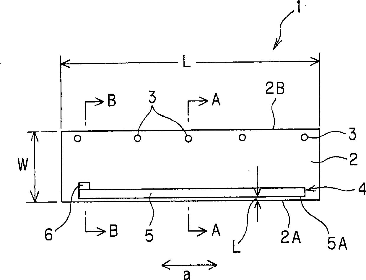
[0082] A SUS301 plate with a thickness of 0.1 mm, a width of 18 mm, and a length of 240 mm was prepared as a supporting member. The support member uses a modulus of elasticity of 1.9×10 4 kg / mm 2 , Sectional moment of inertia (Iz) is 1.5E-03 material. In addition, the modulus of elasticity of the supporting member was measured using the metal material tensile test method JIS Z2241 method. In addition, the section moment of inertia (Iz) can be calculated from the cross-sectional shape of the supporting member. Since the cross-sectional shape is a rectangle, the above formula 4(bh 3 / 12) calculation. The result is Iz=18×0.1 3 / 12=1.5E-03.
[0083] Next, six kinds of mixtures of liquid silicone rubber and curing agent (mixtures A to F) were prepared. Next, use each mixture, and use Figure 7 , Figure 8 Six types of developing blades (samples 1 to 6) were produced using the injection molding die shown and the above-mentioned supporting member. The 25% modulus of the blad...
Embodiment 2
[0093] The same SUS301 plate as in Example 1 was prepared as a supporting member.
[0094] Next, prepare NBR and FKM (LT303 manufactured by Daikin Industries, Ltd.), silicone rubber (X34-1595-B manufactured by Shin-Etsu Chemical Co., Ltd.) Blade members were formed, and developing blades (sample 7, sample 8) were manufactured respectively. The 25% modulus of the blade members constituting these developing blades was measured in the same manner as in Example 1. As a result, it was found that the developing blade (sample 7) using NBR was 0.7 MPa, while the developing blade using FKM and silicone rubber was 0.7 MPa. (Sample 8) was 0.5 MPa. In addition, the section moment of inertia (Iz) of the blade member was 7E-01 in both samples 7 and 8.
[0095]In the same manner as in Example 1, the amount of warpage of each of the developing blades produced in the above-mentioned manner was measured. As a result, it was found that the amount of warpage of the developing blade (sample 7) u...
Embodiment 3
[0097] The same SUS301 plate as in Example 1 was prepared as a supporting member.
[0098] Next, the same mixture B of liquid silicone rubber and curing agent as used in Example 1 was prepared. Next, five types of developing blades (Samples 9 to 13) having different cross-sectional moments of inertia of the blade members were produced by the same injection molding as in Example 1, except using injection molding dies with different cavity volumes in the upper mold. . The sectional moments of inertia of blade members constituting the five types of developing blades (samples 9 to 13) produced in this way are shown in Table 2 below. In addition, the 25% modulus of the blade member constituting each developing blade was 0.6 MPa.
[0099] The amount of warpage of five types of developing blades (samples 9 to 13) produced as above was measured by the same method as in Example 1, and the results are shown in Table 2 below.
[0100] Table 2
[0101]
[0102] As shown in Table 2,...
PUM
 Abstract
Description
Claims
Application Information
 - Generate Ideas
- Intellectual Property
- Life Sciences
- Materials
- Tech Scout
- Unparalleled Data Quality
- Higher Quality Content
- 60% Fewer Hallucinations
Browse by: Latest US Patents, China's latest patents, Technical Efficacy Thesaurus, Application Domain, Technology Topic, Popular Technical Reports.
© 2025 PatSnap. All rights reserved.Legal|Privacy policy|Modern Slavery Act Transparency Statement|Sitemap|About US| Contact US: help@patsnap.com


