Aerodynamic structure for vehicle
An aerodynamic and vehicle technology, applied in the direction of vehicle components, superstructure, superstructure sub-assembly, etc., can solve problems such as difficult to obtain performance, and achieve the effect of effective rectification and good effect
- Summary
- Abstract
- Description
- Claims
- Application Information
AI Technical Summary
Problems solved by technology
Method used
Image
Examples
no. 2 Embodiment approach
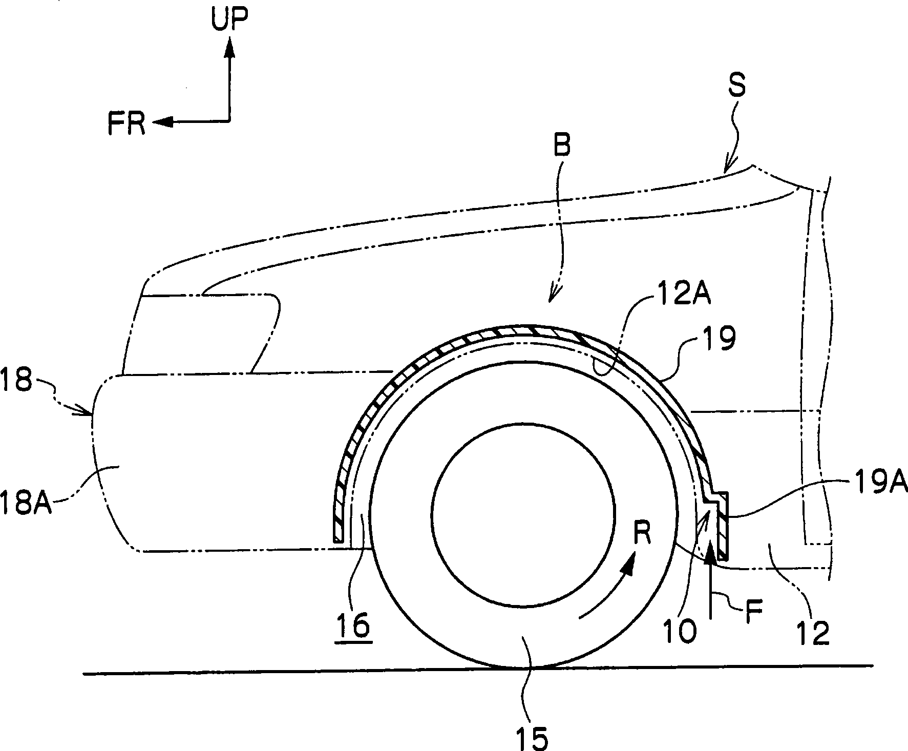
[0077] Figure 4 In the figure, the fixed aerodynamic stabilizer 20 as the vehicle wheel house structure in the second embodiment of the present invention is shown in a schematic side view. As shown in this figure, the fixed aerodynamic stabilizer 20 is provided as a wind-receiving surface facing downward on the inner side in the vehicle width direction behind the rotation shaft 15A of the front wheel 15 . In this embodiment, the fixed aerodynamic stabilizer 20 is integrally formed with the standing wall portion 14A of the wheel house liner 14 facing the inward surface of the front wheel 15 in the vehicle width direction.
[0078] Specifically, as shown in FIG. 5(A) and FIG. 5(B), the aerodynamic stabilizer 20 is fixed as a recessed portion 14B that opens downward and outwardly in the vehicle width direction at about the rear half of the vertical wall portion 14A. The downwardly facing step portion (recessed wall), that is, the air flow colliding wall, is integrally formed wi...
no. 5 Embodiment approach
[0108] Figure 12 In the figure, the main part of the vehicle wheel house structure 50 in 5th Embodiment of this invention is shown in perspective view. As shown in this figure, the wheel house structure 50 for a vehicle differs from the wheel house structure 21 for a vehicle in the third embodiment in that the locking grooves 22 and the locking grooves 32 are surrounded by ribs 52 , 32 in the vehicle width direction. 54 are distinguished.
[0109] In the present embodiment, a plurality of (two) ribs 52 are disposed on each locking groove 22, and each locking groove 22 is divided into three unit locking grooves 22D. In addition, a plurality of (two) ribs 54 are arranged on the locking groove 32, and each locking groove 32 is divided into three unit locking grooves 32D. The rib 52 is integrally formed with the fender liner 19 and the rib 54 is integrally formed with the rear wheel speed reducer 30 . Other structures of the vehicle wheel house structure 50 , including parts n...
no. 6 Embodiment approach
[0113] Figure 13 In the figure, the main part of the vehicle wheel house structure 60 in 6th Embodiment is shown in side view. As shown in the figure, the wheel house structure 60 for a vehicle differs from the wheel house structure 21 for a vehicle in the third embodiment in that it has a rear wheel speed reduction cover 62 instead of the rear wheel speed reduction cover 30 .
[0114] The rear wheel speed reducer cover 62 is formed, for example, in a plate shape from a material such as rubber, and has flexibility. The rear wheel speed reducer 62 has a guide surface 34 that forms a stopper groove 32 with the extension 11C (bracket 11 ), and performs the same function as the rear wheel speed reducer 30 . The side wall 38 may also be provided on the rear wheel speed reducer 62 , but is preferably provided on the fender bushing 19 , the bracket 11 , a not-shown fender garnish, and the like. Other structures of the vehicle wheel house structure 60 are the same as the correspond...
PUM
 Abstract
Description
Claims
Application Information
 - R&D
- Intellectual Property
- Life Sciences
- Materials
- Tech Scout
- Unparalleled Data Quality
- Higher Quality Content
- 60% Fewer Hallucinations
Browse by: Latest US Patents, China's latest patents, Technical Efficacy Thesaurus, Application Domain, Technology Topic, Popular Technical Reports.
© 2025 PatSnap. All rights reserved.Legal|Privacy policy|Modern Slavery Act Transparency Statement|Sitemap|About US| Contact US: help@patsnap.com


