Developing device and image forming apparatus having the same
A developing device and image technology, applied in the field of developing devices and image forming devices, can solve the problems of toner flying dust, toner failure to adhere, insufficient charging, etc., and achieve the effect of reducing re-floating
- Summary
- Abstract
- Description
- Claims
- Application Information
AI Technical Summary
Problems solved by technology
Method used
Image

Examples
Embodiment approach 1
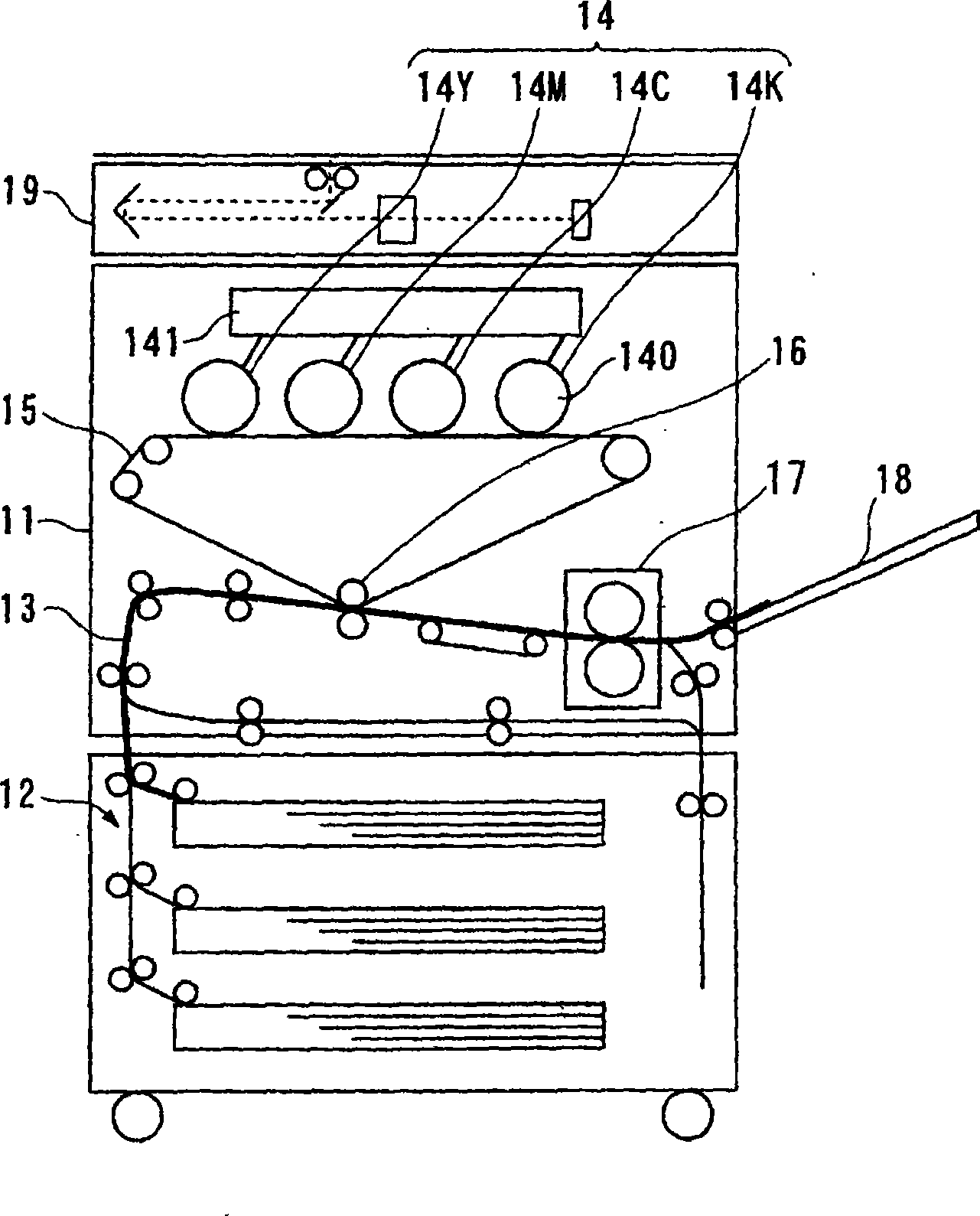
[0047] figure 2 The overall configuration of Embodiment 1 in which a so-called tandem type electrophotographic apparatus equipped with the developing device of the present invention is shown. This electrophotographic device can be applied to a copier or a printer as an example.
[0048] Such as figure 2 As shown, the electrophotographic device has a device main body 11 for imaging. At the bottom of the device main body 11, a paper feeder 12 that can supply paper to the device 11 is provided. Document reading section 19 .
[0049] Here, an image forming unit 14 using a plurality of electrophotographic color components (for example, yellow (Y), magenta (M), cyan (C), and black (K)) is mounted on the main body 11 of the apparatus (specifically, 14Y, 14M, 14C, and 14K), an intermediate transfer belt 15 is provided that temporarily holds and conveys the toner images of the respective color components formed by the image forming units 14 onto paper.
[0050] In addition, in th...
Embodiment approach 2
[0068] Next, for the developing device 20 using the second embodiment of the present invention, use Figure 5 , 6 for explanation.
[0069] Figure 5 is the same as that of Embodiment 1 image 3 Corresponding longitudinal sectional explanatory diagram, Fig. 6 is that of Embodiment 1 Figure 4 Equivalent axial section illustration. In addition, in the second embodiment, components and configurations having the same functions as those in the first embodiment are denoted by the same reference numerals, and detailed description thereof will be omitted.
[0070] Such as Figure 5 As shown, as the developing device 20 , a partition 48 is provided inside the developing container 21 , and has a lower developer stirring chamber 56 and an upper developer supply chamber 57 partitioned up and down by the partition 48 . One end of the partition 48 is fixed to the side of the developing container 21 , while the other end extends toward the developing roller 22 . In addition, the space...
Embodiment approach 3
[0077] Next, for the developing device according to Embodiment 3 using the present invention, use Figure 7 , 8 Be explained.
[0078] Figure 7 is the same as that of Embodiment 1 image 3 The corresponding longitudinal section explanatory drawing, Figure 8 is the same as that of Embodiment 1 Figure 4 Equivalent axial section illustration. In addition, in Embodiment 3, components and configurations having the same functions as those in Embodiment 1 and Embodiment 2 described above are denoted by the same reference numerals, and detailed descriptions thereof are omitted.
[0079] Such as Figure 7 As shown, the developing device 20 has, inside the developing container 21 : a developer stirring chamber 76 ; a developer supply chamber 77 adjacent to the developer stirring chamber 76 ; and a recovery chamber 78 adjacent to the developer supply chamber 77 . Such as Figure 8 As shown, the developer stirring chamber 76 and the developer supply chamber 77 are partitioned b...
PUM
 Abstract
Description
Claims
Application Information
 - R&D
- Intellectual Property
- Life Sciences
- Materials
- Tech Scout
- Unparalleled Data Quality
- Higher Quality Content
- 60% Fewer Hallucinations
Browse by: Latest US Patents, China's latest patents, Technical Efficacy Thesaurus, Application Domain, Technology Topic, Popular Technical Reports.
© 2025 PatSnap. All rights reserved.Legal|Privacy policy|Modern Slavery Act Transparency Statement|Sitemap|About US| Contact US: help@patsnap.com