
Display device

A display device and display surface technology, applied in static indicators, instruments, discharge tubes, etc., can solve problems such as unit brightness deviation, and achieve the effect of reducing uneven brightness

Inactive Publication Date: 2009-04-01
SHINODA PLASMA
View PDF2 Cites 1 Cited by
  • Summary
  • Abstract
  • Description
  • Claims
  • Application Information

AI Technical Summary

Problems solved by technology

Therefore, if one image is displayed in multiple units, there will be a difference in luminance between the units

Method used


Image

  • Display device
  • Display device
  • Display device

Examples


Embodiment Construction

[0029] Embodiments of the present invention will be described below with reference to the drawings. In the drawings, the same reference numerals are attached to the same constituent elements.

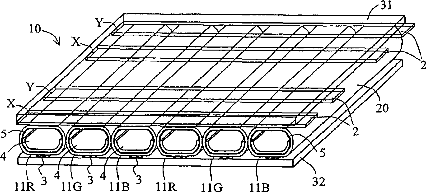
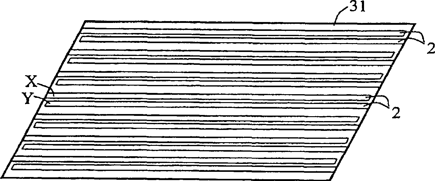
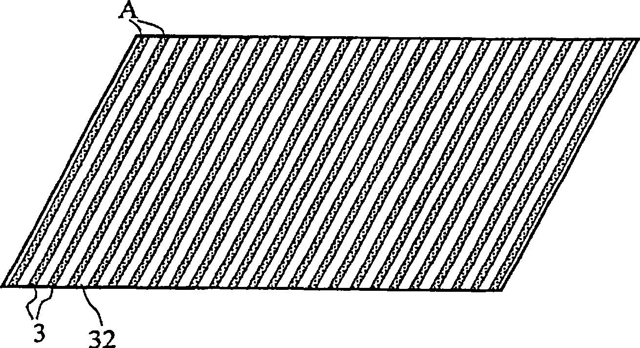
[0030] figure 1 A partial schematic configuration of an array of plasma tubes or gas discharge tubes 11R, 11G, and 11B of a general color display device 10 is briefly illustrated. exist figure 1Among them, the display device 10 includes: an array of transparent and elongated color plasma tubes 11R, 11G, and 11B arranged parallel to each other, a front side support substrate 31 formed by a support sheet or a thin substrate on the transparent front side, a transparent or opaque The back side support substrate 32 formed of a support sheet or a thin substrate, a plurality of display electrode pairs or main electrode pairs 2 , and a plurality of signal electrodes or address electrodes 3 are formed on the back side. exist figure 1 Among them, X represents a sustain electrode or an X elect...


PUM


Abstract

In a display device (10), a scan-driving circuit (702) supplies a scanning voltage, and then a maintaining voltage pulse, to one side of display electrodes (Y1,..., Yj,..., Yn) of each pair of a plurality of pairs of display electrodes in adjacent two units (314, 316) of a plurality of units, at least one of at least two maintaining voltage circuits supplies a maintaining voltage pulse potential to the other side of display electrodes (X1,..., Xj,..., Xn) of each pair of a plurality of pairs of display electrodes of at least one unit (502) at the most outside of a plurality of units.

Description

technical field [0001] The present invention relates to a large display device, in particular to an electrical connection to a drive circuit for display electrodes of a large display device formed of a plurality of plasma tube arrays having phosphor layers inside. Background technique [0002] In a plasma display panel (PDP), the plasma is discharged in a closed discharge space of a large number of small grids (cells) arranged vertically and horizontally, and the phosphor is excited to emit light by the 147nm ultraviolet light emitted from the discharge plasma. The cell space is formed between two overlapping sheets of flat glass. On the other hand, in a plasma tube array (PTA), a phosphor layer is formed in an elongated glass tube or a support member on which the phosphor layer is formed is inserted, and many grid spaces are formed in the tube. By arranging a large number of such plasma tubes side by side, a large display screen of, for example, 6 m×3 m can be formed. In ...

Claims


Application Information

Patent Timeline
Patent Type & Authority Applications(China)
IPC IPC(8): G09G3/28G09G3/20H01J11/00G09G3/291G09G3/294G09G3/296G09G3/298
CPCG09G2300/026G09G3/2983G09G3/296G09G3/293
Inventor 石本学平川仁粟本健司
Owner SHINODA PLASMA
Learn More