
Wet friction material

A friction part, wet technology, applied in the direction of friction linings, friction clutches, clutches, etc., can solve the problems of ATF being difficult to be discharged, the total area of ​​the oil passage is limited, etc., and achieve the effect of high drag torque reduction effect and large reduction effect.

Inactive Publication Date: 2009-04-01
AISIN CHEM CO LTD
View PDF3 Cites 16 Cited by
  • Summary
  • Abstract
  • Description
  • Claims
  • Application Information

AI Technical Summary

Problems solved by technology

[0004] However, in order to improve the responsiveness of the hydraulic clutch, the distance between the fan-shaped friction member and the release plate is set to be small. In addition, in order to sufficiently ensure the torque transmission capacity when the hydraulic clutch is connected, the fan-shaped friction member The total area occupied by the oil passage is limited
As a result, when the hydraulic clutch is not connected, it is difficult to discharge the ATF remaining between the fan-shaped friction member and the release plate, and there is a problem that ATF drag torque is generated due to the relative rotation of the two plates.

Method used


Image

  • Wet friction material
  • Wet friction material
  • Wet friction material

Examples


Embodiment approach 1

First, refer to Figure 1 to Figure 5 The wet friction material according to Embodiment 1 of the present invention will be described.

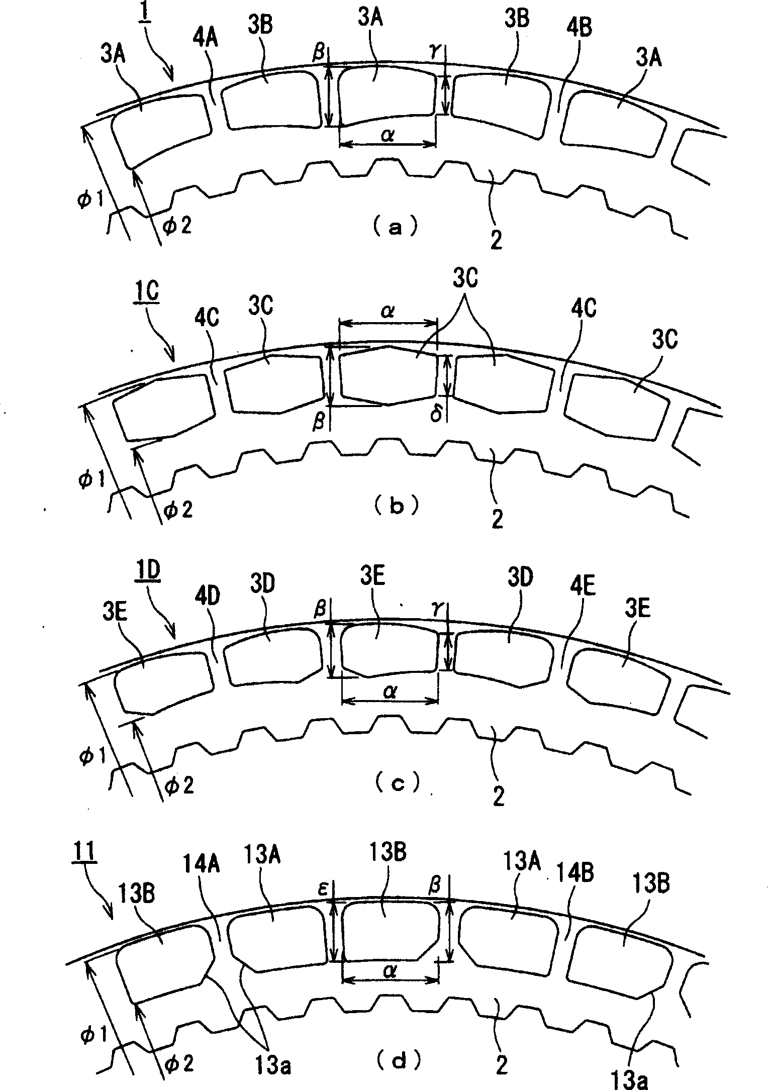
[0044] figure 1 (a) is a partial plan view showing a part of a wet friction material (Example 1) according to Embodiment 1 of the present invention, and (b) is a wet friction material (Example 2) showing a first modified example of Embodiment 1 of the present invention. ), (c) is a partial plan view showing a part of a wet friction material (Example 3) according to a second modified example of Embodiment 1 of the present invention, and (d) is a wet friction material showing a prior art Partial plan view of a part of (Comparative Example).

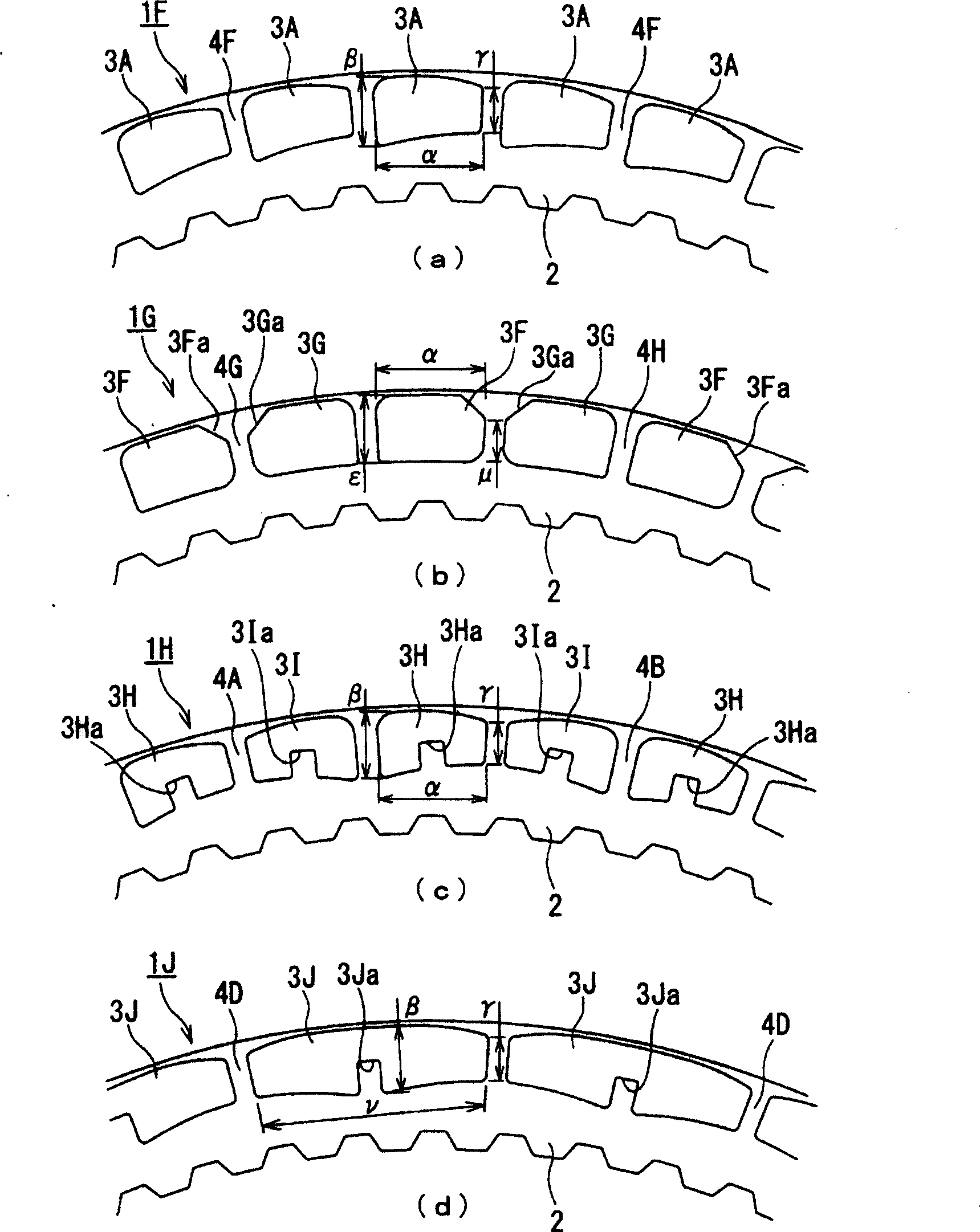
[0045] figure 2(a) is a partial plan view showing a part of a wet friction material according to a third modified example of Embodiment 1 of the present invention, and (b) is a partial plan view showing a part of a wet friction material according to a fourth modified example of Embodiment 1 of the presen...

Embodiment approach 2

Refer below Image 6 and Figure 7 , the wet friction material according to Embodiment 2 of the present invention will be described. Image 6 (a) is a partial plan view showing a part of the wet friction material according to Embodiment 2 of the present invention, (b) is a partial cross-sectional view showing a vertical section of the wet friction material according to Embodiment 2 of the present invention, and (c) is a partial sectional view showing the present invention. (d) is a partial plan view showing a part of a wet friction material according to a second modification of Embodiment 2 of the present invention.

[0107] Figure 7 (a) is a partial plan view showing a part of a wet friction material according to a third modified example of Embodiment 2 of the present invention, and (b) is a partial plan view showing a part of a wet friction material according to a fourth modified example of Embodiment 2 of the present invention Plan view, (c) is a partial plan view showin...


PUM


Abstract

In a wet friction material, to be able to obtain a more significant drag torque reduction effect certainly by making it easy to discharge a lubricating oil which is supplied from an inner peripheral side of a core metal into an outer peripheral side and by preventing a stirred torque from increasing by generating oil retained at an outer periphery, and moreover to be able to obtain a more significant drag torque reduction effect even in case of a specification that there is no lubricating oil supply from the inner peripheral side. In a segment-type friction material 1, it promotes ATF to discharge into outside a diameter and enhances a cavitation by giving R processing to an inner periphery and an outer periphery of segment pieces 3A, 3B so as to shorten an oil groove 4A, and yet it can restrain a stirred torque resulting from forming oil retained by ATF caused by that a space in the outer peripheral side is secured by giving R processing to the outer periphery of segment pieces 3A, 3B.

Description

technical field [0001] The present invention relates to a wet friction member that obtains torque by applying high pressure to the opposing surfaces in a state immersed in oil, that is, it involves bonding the base material of the friction member that has been cut into segments on a flat annular core bone The fan-shaped friction part formed on both sides or one side of the whole circumference, or the two sides or one side of the ring-shaped friction part where the base material of the ring-shaped friction part is bonded to both sides or one side of the flat ring-shaped core bone A ring-shaped friction member formed by pressing or cutting on one side and forming multiple oil grooves in the radial direction. Background technique [0002] In recent years, as a wet friction part, with the aim of reducing the cost by improving the utilization rate of materials and reducing the fuel consumption in vehicles by reducing the drag torque, the cutting edge The friction element base ma...

Claims


Application Information

Patent Timeline
Patent Type & Authority Applications(China)
IPC IPC(8): F16D69/00F16D13/64F16D65/12
CPCY10T428/24612F16D13/648F16D2069/004F16D13/74
Inventor 东岛祐子铃木雅登
Owner AISIN CHEM CO LTD
Learn More