Design proposal for grinding copper holder locking notch and clamping device
What is Al technical title?
Al technical title is built by PatSnap Al team. It summarizes the technical point description of the patent document.
A design method and clamping device technology, applied in metal processing equipment, grinding/polishing equipment, grinding machines, etc., to achieve the effect of high precision, small size, and stable clamping device
Inactive Publication Date: 2010-12-08
LUOYANG BEARING SCI & TECH CO LTD
View PDF0 Cites 0 Cited by
Summary
Abstract
Description
Claims
Application Information
AI Technical Summary
This helps you quickly interpret patents by identifying the three key elements:
Problems solved by technology
Method used
Benefits of technology
Problems solved by technology
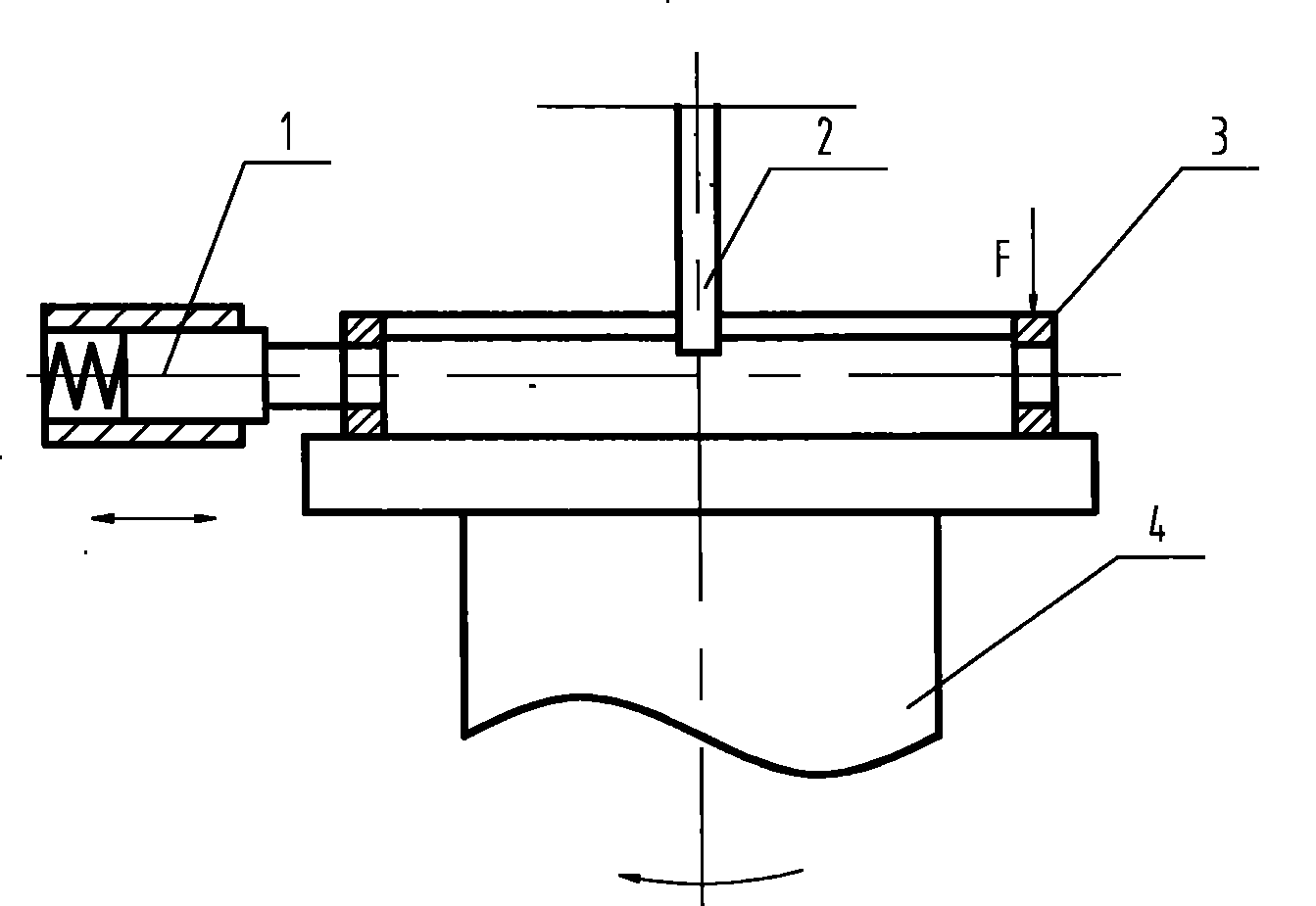
[0003] The indexing and positioning of the above-mentioned special fixtures are convenient and quick, but due to the small size of the cage to be processed and the large grinding wheel, the pressing finger is too close to the grinding wheel. If you don't pay attention, your fingers will be worn by the grinding wheel and cause unnecessary accidents
Method used
Image
Click on the blue label to locate the original text in one second.
Reading with bidirectional positioning of images and text.
Examples
Embodiment Construction
[0018] The design method of the grinding and processing copper cage lock of the present invention mainly includes the following contents:
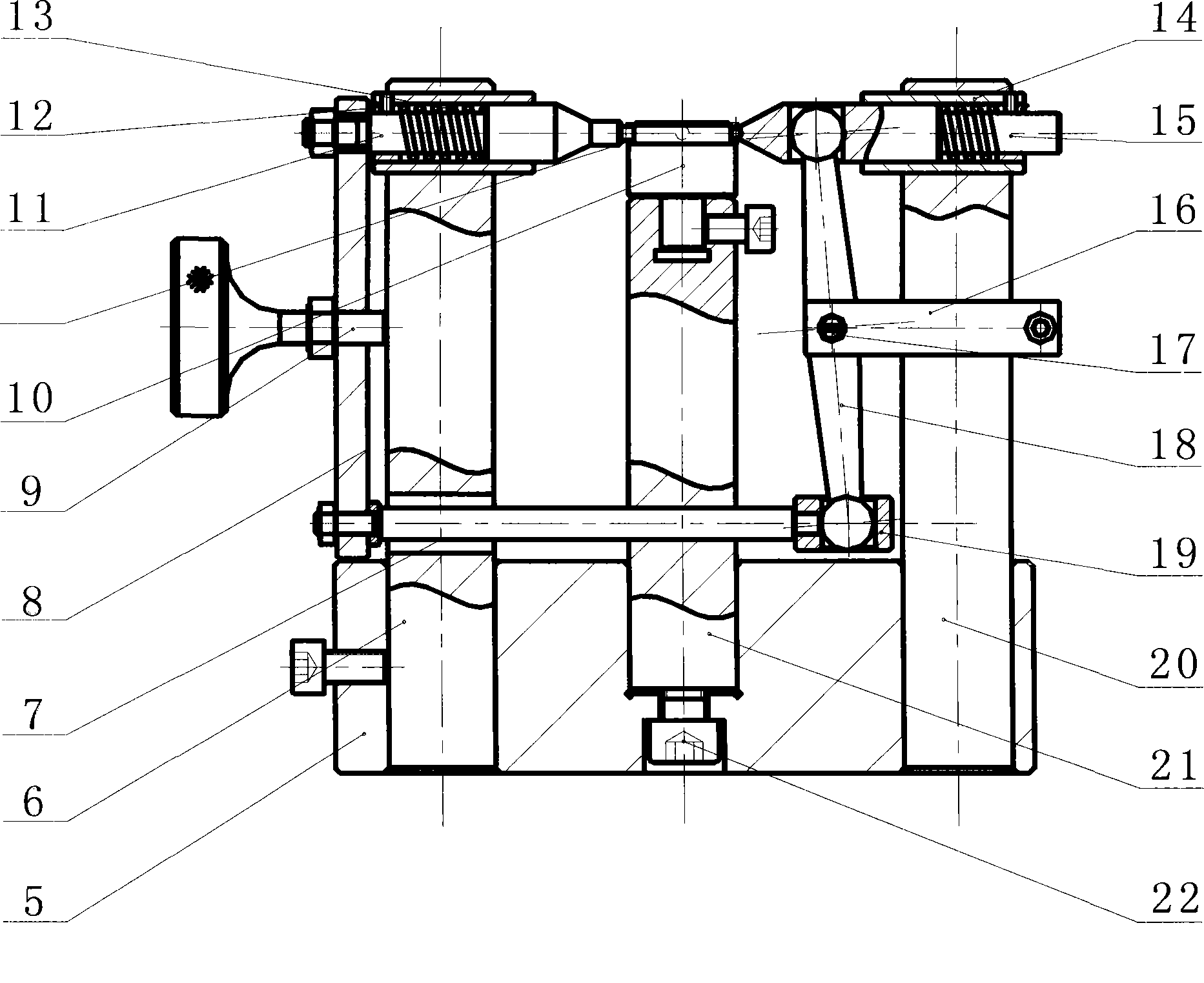
[0019] 1) Design two positioning pins that can move left and right respectively to clamp the cage to be processed. The axial clamping force of the positioning pin comes from the compression spring, and the axes of the two positioning pins should be concentric;
[0020] 2) The cage to be processed is placed on the positioning mandrel, and the positioning mandrel is required to be adjusted up and down;
[0021] 3) Pulling the left and right positioning pins must be a simultaneous linkage process, which can only be performed by one linkage mechanism;
[0022] 4) The whole device should be compact in structure, balanced in clamping force and able to pull the left and right positioning pins outward or clamp inward at the same time, so as to achieve the purpose of safely pressing or picking and placing the cage to be processed.
[0023] combine...
PUM
Abstract
The invention provides a design proposal used for grinding and processing the locking notch of a copper retaining frame, and a clamping device; wherein, the clamping device consists of a base 5, a left column 6, a pulling pin 7, a connecting plate 8, a pulling handle 9, a positioning core shaft 10, a left positioning pin 11, a retaining ring 12, a pressure spring 13, a guide sleeve 14, a right positioning pin 15, a pulling fork frame 16, a pin shaft 17, a pulling fork 18, a position limit block 19, a right column 20, a positioning column 21 and a screw 22; the positioning pin which can move to the left side and the right side is used for clamping the retaining frame 3 to be processed; the axial clamping force of the positioning pin comes from the pressure spring; the axis center lines of the two positioning pins are concentric; the retaining frame to be processed is arranged on a positioning core shaft, the positioning core shaft can be adjusted upwards and downwards; the pulling of left positioning pin and the right positioning pin must be a linked process and is carried out by the pulling pin, the connecting plate, the pulling handle, the pulling fork frame, the pin shaft, the pulling fork and the position limit block. The clamping device has compact structure and balanced clamping force, and can lead the left positioning pin and the right positioning pin to be pulled out orclamped inwards simultaneously, thus achieving the compressing or loosening the retaining frame to be processed.
Description
technical field [0001] The invention belongs to the technical field of bearing cage processing, in particular to a design method and a clamping device for grinding and cutting a lock port of a copper cage. Background technique [0002] figure 1 It is a copper solid cage with a small size and a narrow width. When grinding and cutting its lock, it is usually used figure 2 The schematic diagram of the conventional clamping device for grinding and cutting locks is shown. Place the cage 3 to be processed on a fixed mandrel 4, turn the cage slightly so that the pocket positioning pin 1 with elastic pressure is inserted into a pocket of the cage for indexing and unilateral compression, and at the same time The finger pressure F acts on the opposite side of the cage, so that the cage as a whole is in a compressed state, and the grinding wheel 2 is moved back and forth to complete the grinding and cutting of one of the locks. Repeat the above process to complete the grinding an...
Claims
Application Information
Patent Timeline
Application Date:The date an application was filed.
Publication Date:The date a patent or application was officially published.
First Publication Date:The earliest publication date of a patent with the same application number.
Issue Date:Publication date of the patent grant document.
PCT Entry Date:The Entry date of PCT National Phase.
Estimated Expiry Date:The statutory expiry date of a patent right according to the Patent Law, and it is the longest term of protection that the patent right can achieve without the termination of the patent right due to other reasons(Term extension factor has been taken into account ).
Invalid Date:Actual expiry date is based on effective date or publication date of legal transaction data of invalid patent.