Container after-frame assembling tyre and assembling method

A container, rear frame technology, used in auxiliary devices, auxiliary welding equipment, welding/cutting auxiliary equipment, etc.

Inactive Publication Date: 2012-01-11
CHINA INTERNATIONAL MARINE CONTAINERS (GROUP) CO LTD +1
View PDF6 Cites 0 Cited by
  • Summary
  • Abstract
  • Description
  • Claims
  • Application Information

AI Technical Summary

Problems solved by technology

[0003]One purpose of the present invention is to solve the problem in the prior art that the size of the rear frame cannot be guaranteed to be stable when producing the rear frame of the container
[0004] Another object of the present invention is to provide a method for assembling the rear frame to solve the problem of unstable size of the assembled rear frame in the prior art

Method used


Image

  • Container after-frame assembling tyre and assembling method
  • Container after-frame assembling tyre and assembling method
  • Container after-frame assembling tyre and assembling method

Examples


Embodiment Construction

[0033] The rear frame assembly tire of the present invention will be described below with reference to the accompanying drawings.

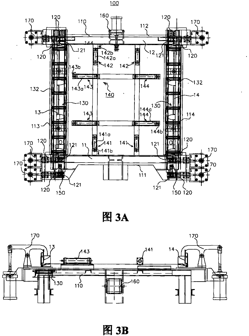
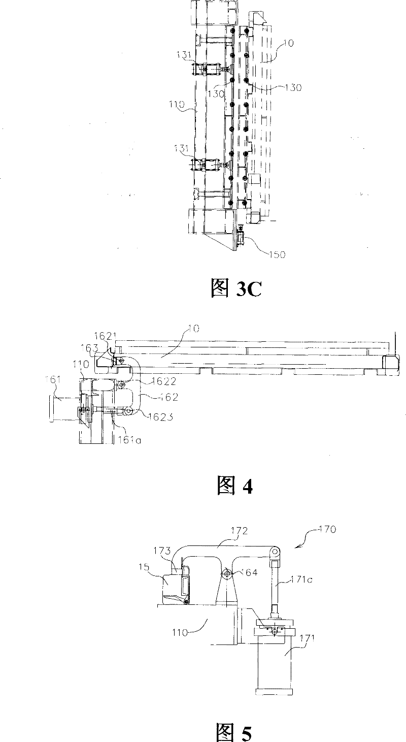
[0034] like Figures 3A to 3C As shown, the rear frame assembling tire 100 of the present invention includes an in-frame positioning device 140 in addition to the previously described chassis 110 , a plurality of horizontal positioning blocks 120 , a plurality of vertical positioning blocks 121 and a roller passing device 130 . refer to Figure 3A , 3B , the frame positioning device 140 is arranged in the middle part of the bottom frame 110, and is surrounded by the end beam and the side beam of the bottom frame. The in-frame positioning device 140 includes four groups of pressing devices 141 , 142 , 143 and 144 , which are respectively disposed corresponding to the two end beams and the two side beams of the bottom frame 110 . Preferably, each set of pressing devices may include two pressing devices arranged in parallel. The main bodies 141a,...


PUM


Abstract

The invention provides a container rear frame assembly tyre; the rear frame comprises an upper crossbeam, a lower crossbeam, a left corner column, a right corner column and a corner fittings which is formed by welding the left corner column and the right corner column together; the upper crossbeam, the lower crossbeam, the left corner column and the right corner column are connected with each other; the rear frame assembly tyre comprises an underframe which is used for arranging all parts of the rear frame which comprises two end beams and two side beams, a vertical positioning block which isarranged on the underframe and used for limiting the positions of the upper crossbeam, the lower crossbeam, the left corner column and the right corner column in the vertical direction, and a horizontal positioning block which is arranged on the underframe and used for limiting the positions of the upper crossbeam, the lower crossbeam, the left corner column and the right corner column in the horizontal direction; the rear frame assembly tyre also comprises an internal positioning device which is arranged at the middle part of the underframe; the internal positioning device comprises four groups of push-press devices which are respectively corresponding to the two end beams and the two side beams of the underframe; each group comprises at least a push-press device; each push-press device comprises a mainbody which is fixed on the underframe and a pushing rod which can extend out of the main body facing the corresponding end beam or side beam of the underframe.

Description

technical field [0001] The invention relates to the field of container production, in particular, it is designed to assemble tires for the rear frame of the container rear frame. Background technique [0002] like figure 1 As shown, the rear frame 10 of the container is usually a frame body composed of an upper beam 11, a lower beam 12, a left corner post 13, and a right corner post 14, and corner fittings 15 are respectively arranged at the four corners of the frame body. In the prior art, the above-mentioned rear frame components are usually assembled on the rear frame assembly tire to form the rear frame. Usually, the corner fittings 15 and the left and right corner posts are pre-welded into one body before assembly. like figure 2 As shown, the rear frame assembly tire in the prior art includes a chassis 110 for placing various components of the rear frame. Wherein, the upper crossbeam 11 and the lower crossbeam 12 are respectively placed on the two opposite end bea...

Claims


Application Information

Patent Timeline
Patent Type & Authority Patents(China)
IPC IPC(8): B23K37/053B23K37/04B23K37/00
Inventor 赵宝东赵建朝
Owner CHINA INTERNATIONAL MARINE CONTAINERS (GROUP) CO LTD
Why Eureka
Try Eureka